Se quiser comprar os itens adicionais que voc selecionou para poder receber esta oferta. 0000002580 00000 n 511 42
The Sensorwell team has been working as a competent and reliable trading partner in the field of sensors, automation and security technology since 2005. Its universal spare parts further add to the ease of maintenance. Manualzz provides technical documentation library and question & answer platform.Its a community-based project which helps to repair anything.  }); Warrington This website uses cookies to improve your experience. 0000033324 00000 n
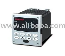
The universal digital controller possesses adequate power and cost effectively brings with it several advanced features such as enhanced set point programming, fast scanning and on-board diagnostics. UNIVERSAL DIGITAL CONTROLLER, UDC3500, ELECTRO MECHANICAL RELAY, ENGLISH MANUAL (HARD COPY), PDF Product Datasheet for DC3500-EE-0000-160-00000-E0-0
0000056145 00000 n
Mit der Nutzung unserer Seite erklren Sie sich damit einverstanden, dass wir Cookies verwenden.
}); Warrington This website uses cookies to improve your experience. 0000033324 00000 n
The universal digital controller possesses adequate power and cost effectively brings with it several advanced features such as enhanced set point programming, fast scanning and on-board diagnostics. UNIVERSAL DIGITAL CONTROLLER, UDC3500, ELECTRO MECHANICAL RELAY, ENGLISH MANUAL (HARD COPY), PDF Product Datasheet for DC3500-EE-0000-160-00000-E0-0
0000056145 00000 n
Mit der Nutzung unserer Seite erklren Sie sich damit einverstanden, dass wir Cookies verwenden.
 7 Drumhead Place
 0000013662 00000 n
trailer
 UDC 3500 is a next-generation universal controller in the popular DIN size. Out of these, the cookies that are categorized as necessary are stored on your browser as they are essential for the working of basic functionalities of the website. The universal digital controller possesses adequate power and cost effectively brings with it several advanced features such as enhanced set point programming, fast scanning and on-board diagnostics. 0000032679 00000 n
0000001085 00000 n
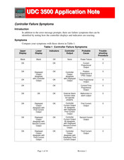
Universal digital limit controller (120 pages), Honeywell universal digital controller product manual (243 pages), Manual will be automatically added to "My Manuals", Figure 1-2 Screen Capture of Process Instrument Explorer Running on a Pocket PC, Figure 1-3 Depiction of Infrared Communications, Figure 2-11 Optional Analog Input Jumper Positions, Control and Alarm Relay Contact Information, Table 2-2 Control Relay Contact Information, Table 2-3 Alarm Relay Contact Information, Figure 2-2 Mounting Dimensions (Not to Scale), Table 2-6 Single or Cascade Loop Controller - Loop 1 Output Functionality and Restrictions, Table 2-7 Dual Loop Controller - Loop 2 Output Functionality and Restrictions, Figure 2-9 HLAI Inputs 2 and 4 Connections, Figure 2-10 HLAI Inputs 3 and 5 Connections, Figure 2-14 Output #2 - Electromechanical Relay Output, Figure 2-15 Output #2 - Solid State Relay Output, Figure 2-16 Output #2 - Open Collector Output- Third, Figure 2-17 Output #2 - Third Current Output, Figure 2-18 Output #2 - Dual Relay Output for Time Duplex, Figure 2-19 Output #2 - Dual Relay Output for Position Proportional or Three Position Step Control, Figure 2-20 RS-422/485 Communications Option Connections, Figure 2-21 Ethernet Communications Option with Adaptor Board, Table 2-8 Terminals for Connecting a UDC to a MDI Compliant Hub or Switch Utilizing a Cross-Over Cable, Figure 2-22 Ethernet Communications Option Without Adaptor Board, Table 2-9 Terminals for Connecting a UDC Directly to a PC Utilizing a Straight-Through Cable, Figure 2-24 Optional Electromechanical Relay Outputs, Figure 2-25 Transmitter Power for 4-20 Ma - 2 Wire Transmitter Using Open Collector Output, Figure 2-26 Transmitter Power for 4-20 Ma - 2 Wire Transmitter Using Second Current Output, Table 3-5 TUNING 2 Group Function Prompts, Table 3-7 ACCUTUNE Group Function Prompts, Table 3-8 ALGORTHM Group Function Prompts, Figure 3-2 Example of Eight Segment Characterizer, Table 3-12 INPUT 1 Group Function Prompts, Table 3-13 INPUT 2 Group Function Prompts, Table 3-14 INPUT 3 Group Function Prompts, Table 3-15 INPUT 4 Group Function Prompts, Table 3-16 INPUT 5 Group Function Prompts, Table 3-17 CONTROL Group Function Prompts, Table 3-18 CONTROL2 Group Function Prompts, Table 3-20 Communications Group Function Prompts, Table 3-23 MAINTENANCE Group Function Prompts, Table 3-24 DISPLAY Group Function Prompts, Table 3-25 READ MAINTENANCE Group Function Prompts, Table 3-26 TIME EVT Group Function Prompts, Tool Ethernet and Email Configuration Screens, 4 Monitoring and Operating the Controller, Table 4-1 Procedure to Enter a Security Code, Table 4-3 Lower Display Key Parameter Prompts, Table 4-4 Procedure for Starting up the Controller, Table 4-7 Procedure for Changing the Local Setpoints, Table 4-8 Procedure for Switching between Setpoints, Table 4-10 Procedure for Using AUTOMATIC TUNE at Start-Up for Duplex Control, Using AUTOMATIC TUNE at Start-Up for Duplex (Heat/Cool), Table 4-11 Procedure for Using BLENDED TUNE at Start-Up for Duplex Control, Using BLENDED TUNE at Start-Up for Duplex (Heat/Cool), Table 4-12 Procedure for Using MANUAL TUNE for Heat Side of Duplex Control, Table 4-13 Procedure for Using MANUAL TUNE for Cool Side of Duplex Control, Using MANUAL TUNE at Start-Up for Duplex (Heat/Cool), Table 4-14 Procedure for Accessing Accutune Error Codes, Table 4-17 Procedure for Switching PID SETS from the Keyboard, Table 4-18 Logic Gates Constraints and Dynamic Operation Status, Table 4-19 Digital Input Option Action on Contact Closure, Table 4-20 Digital Input Combinations "DIG IN1" or "DIG IN2, Table 4-21 Digital Inputs 1 and 2 Combination, Table 4-22 Auto/Manual Station Mode Configuration Procedure, Figure 4-3 Functional Overview Block Diagram of a Single Loop (Loop #1) or Dual Loop Controller (Loop #1 and Loop #2), Figure 4-4 Functional Overview Block Diagram of Internal Cascade Controller, Table 4-23 Procedure for Selecting Two Loop Algorithm, Table 4-24 Digital Display Indication-Two Loops, Table 4-25 Procedure for Displaying Alarm Setpoints, Table 4-26 Procedure for Displaying TPSC Motor Position, Setting a Failsafe Output Value for Restart after a Power Loss, Table 4-27 Procedure for Setting a Failsafe Value, Carbon Potential, Oxygen and Dewpoint Algorithms, Table 4-28 Procedure for Setting a Failsafe Mode, Figure 4-10 Alarm Details Maintenance Screen, Figure 4-11 Status Data Maintenance Screen, Figure 4-12 Diagnostic History Maintenance Screen, Figure 4-13 Ethernet Status Maintenance Screen, Figure 4-14 Healthwatch Data Maintenance Screen, Figure 4-15 Healthwatch Data Reset Screen, Figure 4-17 Real Time Clock Maintenance Screen, Figure 4-19 Configuration Upload in Progress, Figure 4-20 Ethernet Communications Address, Figure 4-21 Configuration Upload in Progress, Table 5-1 Voltage, Milliamp and Resistance Equivalents for Input Range Values, Table 5-3 Set up Wiring Procedure for Thermocouple Inputs Using an Ice Bath, Figure 5-2 Wiring Connections for Thermocouple Inputs Using an Ice Bath, Thermocouple Inputs Using a Thermocouple Source, Table 5-4 Set up Wiring Procedure for Thermocouple Inputs Using a Thermocouple Source, Figure 5-3 Wiring Connections for Thermocouple Inputs Using a Thermocouple Source, Table 5-5 Set up Wiring Procedure for RTD Inputs, Figure 5-4 Wiring Connections for RTD (Resistance Thermometer Device), Radiamatic, Millivolts, Volts, Carbon, Oxygen or Thermocouple Differential Inputs, Table 5-6 Set up Wiring Procedure for Radiamatic, Millivolts, Volts, Carbon, Oxygen or Thermocouple Differential Inputs (Except 0-10 Volts and -1 to 1 Volts), Figure 5-5 Wiring Connections for Radiamatic, Millivolts, Volts, Carbon, Oxygen or Thermocouple Differential, Table 5-7 Procedure to Determine Calibration Voltages for Thermocouple Differential Input Types Other than the Factory Setting, Table 5-8 Set up Wiring Procedure for 0 to 10 Volts or -1 to 1 Volts, Figure 5-6 Wiring Connections for 0 to 10 Volts or -1 to 1 Volts, Table 5-9 Set up Wiring Procedure for Milliampere Inputs, Figure 5-7 Wiring Connections for Milliampere Inputs, Table 5-10 Set up Wiring Procedure for Dual High Level Voltage Inputs, Figure 5-8 Wiring Connections for Dual High Level Voltage Inputs, Table 5-11 Set up Wiring Procedure for Dual High Level Milliampere Inputs, Figure 5-9 Wiring Connections for Dual High Level Milliampere Inputs, Table 6-1 Set up Wiring Procedure for the First Current Output, Figure 6-1 Wiring Connections for Calibrating the First Current Output, Table 6-2 First Current Output Calibration Procedure, Table 6-3 Set up Wiring Procedure for the Second Current Output, Figure 6-2 Wiring Connections for Calibrating the Second Current Output, Table 6-4 Second Current Output Calibration Procedure, Table 6-5 Set up Wiring Procedure for the Third Current Output, Figure 6-3 Wiring Connections for Calibrating Third Current Output, Table 6-6 Third Current Output Calibration Procedure, Position Proportional and Three Position Step Output Calibration, Table 6-7 Position Proportional and Three Position Step Output Calibration Procedure, Table 7-1 Procedure for Identifying the Software Version, Table 7-2 Procedure for Displaying the Status Test Results, Table 7-5 Troubleshooting Power Failure Symptoms, Table 7-6 Troubleshooting Current Output Failure, Table 7-7 Troubleshooting Position Proportional Output Failure, Table 7-8 Troubleshooting Time Proportional Output Failure, Procedure #5 - Current/Time or Time Current/Proportional, Table 7-9 Troubleshooting Current/Time or Time/Current Proportional Output Failure, Table 7-10 Troubleshooting Alarm Relay Output Failure, Table 7-11 Troubleshooting a Keyboard Failure, Table 7-12 Troubleshooting an Analog Input Failure, Table 7-13 Troubleshooting a RS-485 Communications Failure, Table 7-14 Troubleshooting an Ethernet Communications Failure, Table 7-15 Troubleshooting an Email Failure, Table 7-16 Restoring Factory Configuration, Controller Honeywell UDC3500 Quick Start Manual, Controller Honeywell UDC3300 Product Manual, Controller Honeywell UDC3300 Instruction Manual, Controller Honeywell UDC 3300 Product Manual, Controller Honeywell UDC3200 Product Manual, Controller Honeywell UDC3200 series Operator's Manual, Controller Honeywell UDC2500 Product Manual, Controller Honeywell UDC 6300 Product Manual, Controller Honeywell UDC 1000 Micro-Pro Product Manual, Page 22: Process Instrument Explorer Software, Page 23: Figure 1-3 Depiction Of Infrared Communications, Page 32: Figure 2-1 Model Number Interpretation, Page 33: Control And Alarm Relay Contact Information, Page 37: Table 2-5 Permissible Wiring Bundling, Page 39: Table 2-6 Single Or Cascade Loop Controller - Loop 1 Output Functionality And Restrictions, Page 40: Table 2-7 Dual Loop Controller - Loop 2 Output Functionality And Restrictions, Page 46: Figure 2-9 Hlai Inputs 2 And 4 Connections, Page 47: Figure 2-10 Hlai Inputs 3 And 5 Connections, Page 49: Figure 2-14 Output #2 - Electromechanical Relay Output, Page 50: Figure 2-16 Output #2 - Open Collector Output- Third, Page 51: Figure 2-18 Output #2 - Dual Relay Output For Time Duplex, Page 52: Figure 2-20 Rs-422/485 Communications Option Connections, Page 53: Table 2-8 Terminals For Connecting A Udc To A Mdi Compliant Hub Or Switch Utilizing A Cross-Over Cable, Page 54: Table 2-9 Terminals For Connecting A Udc Directly To A Pc Utilizing A Straight-Through Cable, Page 55: Figure 2-24 Optional Electromechanical Relay Outputs, Page 56: Figure 2-26 Transmitter Power For 4-20 Ma - 2 Wire Transmitter Using Second Current Output, Page 77: Table 3-7 Accutune Group Function Prompts, Page 102: Figure 3-2 Example Of Eight Segment Characterizer, Page 169: Table 3-21 Alarms Group Function Prompts, Page 185: Tool Ethernet And Email Configuration Screens, Page 186: Figure 3-4 Email Configuration Screen, Page 195: Monitoring And Operating The Controller, Page 200: Viewing The Operating Parameters, Page 202: Start Up Procedure For Operation, Page 204: What Happens When You Change Modes, Page 205: Table 4-7 Procedure For Changing The Local Setpoints, Page 211: Using Automatic Tune At Start-Up For Duplex (Heat/Cool), Page 212: Using Blended Tune At Start-Up For Duplex (Heat/Cool), Page 213: Using Manual Tune At Start-Up For Duplex (Heat/Cool), Page 216: Using Two Sets Of Tuning Constants, Page 217: Table 4-17 Procedure For Switching Pid Sets From The Keyboard, Page 222: Digital Input Option (Remote Switching), Page 225: Table 4-20 Digital Input Combinations "Dig In1" Or "Dig In2, Page 226: Table 4-21 Digital Inputs 1 And 2 Combination, Page 228: Table 4-22 Auto/Manual Station Mode Configuration Procedure, Page 232: Figure 4-3 Functional Overview Block Diagram Of A Single Loop (Loop #1) Or Dual Loop Controller (Loop #1 And Loop #2), Page 233: Figure 4-4 Functional Overview Block Diagram Of Internal Cascade Controller, Page 234: Configuring Two Loops Of Control, Page 235: Monitoring Two Loops Of Control, Page 237: Table 4-25 Procedure For Displaying Alarm Setpoints, Page 238: Setpoint Programming Event Alarms, Page 239: Three Position Step Control Algorithm, Page 240: Setting A Failsafe Output Value For Restart After A Power Loss, Page 243: Figure 4-6 Carbon Potential Control, Page 246: Table 4-29 Running A Setpoint Ramp, Page 251: Figure 4-7 Ramp/Soak Profile Example, Page 252: Figure 4-8 Program Record Sheet, Page 254: Table 4-31 Run/Monitor Functions, Page 257: Figure 4-10 Alarm Details Maintenance Screen, Page 258: Loop Data Digital Input Details, Page 259: Figure 4-11 Status Data Maintenance Screen, Page 260: Figure 4-12 Diagnostic History Maintenance Screen, Page 261: Figure 4-13 Ethernet Status Maintenance Screen, Page 262: Figure 4-14 Healthwatch Data Maintenance Screen, Page 263: Figure 4-15 Healthwatch Data Reset Screen, Page 264: Figure 4-16 Totalizer Maintenance Screen, Page 265: Figure 4-17 Real Time Clock Maintenance Screen, Page 266: Configuring Your Ethernet Connection, Page 267: Figure 4-19 Configuration Upload In Progress, Page 269: Figure 4-20 Ethernet Communications Address, Page 270: Figure 4-21 Configuration Upload In Progress, Page 272: Minimum And Maximum Range Values, Page 277: Thermocouple Inputs Using A Thermocouple Source, Page 279: Radiamatic, Millivolts, Volts, Carbon, Oxygen Or Thermocouple Differential Inputs, Page 280: Table 5-7 Procedure To Determine Calibration Voltages For Thermocouple Differential Input Types Other Than The Factory Setting, Page 284: Dual High Level Milliamperes Inputs, Page 287: Restore Input Factory Calibration, Page 290: First Current Output Calibration, Page 291: Table 6-2 First Current Output Calibration Procedure, Page 292: Second Current Output Calibration, Page 293: Table 6-4 Second Current Output Calibration Procedure, Page 294: Third Current Output Calibration, Page 295: Table 6-6 Third Current Output Calibration Procedure, Page 296: Position Proportional And Three Position Step Output Calibration, Page 297: Table 6-7 Position Proportional And Three Position Step Output Calibration Procedure, Page 299: Restore Factory Output Calibration, Page 303: Table 7-1 Procedure For Identifying The Software Version, Page 305: Background Tests And Diagnostic Messages, Page 313: Procedure #3 - Position Proportional, Page 316: Procedure #4 - Time Proportional, Page 317: Procedure #5 - Current/Time Or Time Current/Proportional, Page 319: Table 7-10 Troubleshooting Alarm Relay Output Failure, Page 327: Restoring Factory Configuration, Page 334: Table 9-1 Integer Parameter Type, Page 335: Function Code 20 (14H) - Read Configuration Reference Data, Page 336: Table 9-3 Register Parameter Id Address Format For Function Code 20, Page 339: Function Code 21 (15H) - Write Configuration Reference Data, Page 340: Table 9-4 Register Parameter Id Address Format For Function Code 21, Page 342: Modbus Read, Write And Override Parameters Plus Exception Codes, Page 344: Table 10-1 Control Data Parameters, Page 348: Table 10-6 Setpoint Associated Parameters, Page 349: Using A Computer Setpoint (Overriding Controller Setpoint), Page 350: Table 10-8 Computer Setpoint Associated Parameters For Loop 1, Page 351: Table 10-9 Computer Setpoint Associated Parameters For Loop2, Page 413: Table 10-32 Modbus Rtu Data Layer Status Exception Codes.
UDC 3500 is a next-generation universal controller in the popular DIN size. Out of these, the cookies that are categorized as necessary are stored on your browser as they are essential for the working of basic functionalities of the website. The universal digital controller possesses adequate power and cost effectively brings with it several advanced features such as enhanced set point programming, fast scanning and on-board diagnostics. 0000032679 00000 n
0000001085 00000 n
Universal digital limit controller (120 pages), Honeywell universal digital controller product manual (243 pages), Manual will be automatically added to "My Manuals", Figure 1-2 Screen Capture of Process Instrument Explorer Running on a Pocket PC, Figure 1-3 Depiction of Infrared Communications, Figure 2-11 Optional Analog Input Jumper Positions, Control and Alarm Relay Contact Information, Table 2-2 Control Relay Contact Information, Table 2-3 Alarm Relay Contact Information, Figure 2-2 Mounting Dimensions (Not to Scale), Table 2-6 Single or Cascade Loop Controller - Loop 1 Output Functionality and Restrictions, Table 2-7 Dual Loop Controller - Loop 2 Output Functionality and Restrictions, Figure 2-9 HLAI Inputs 2 and 4 Connections, Figure 2-10 HLAI Inputs 3 and 5 Connections, Figure 2-14 Output #2 - Electromechanical Relay Output, Figure 2-15 Output #2 - Solid State Relay Output, Figure 2-16 Output #2 - Open Collector Output- Third, Figure 2-17 Output #2 - Third Current Output, Figure 2-18 Output #2 - Dual Relay Output for Time Duplex, Figure 2-19 Output #2 - Dual Relay Output for Position Proportional or Three Position Step Control, Figure 2-20 RS-422/485 Communications Option Connections, Figure 2-21 Ethernet Communications Option with Adaptor Board, Table 2-8 Terminals for Connecting a UDC to a MDI Compliant Hub or Switch Utilizing a Cross-Over Cable, Figure 2-22 Ethernet Communications Option Without Adaptor Board, Table 2-9 Terminals for Connecting a UDC Directly to a PC Utilizing a Straight-Through Cable, Figure 2-24 Optional Electromechanical Relay Outputs, Figure 2-25 Transmitter Power for 4-20 Ma - 2 Wire Transmitter Using Open Collector Output, Figure 2-26 Transmitter Power for 4-20 Ma - 2 Wire Transmitter Using Second Current Output, Table 3-5 TUNING 2 Group Function Prompts, Table 3-7 ACCUTUNE Group Function Prompts, Table 3-8 ALGORTHM Group Function Prompts, Figure 3-2 Example of Eight Segment Characterizer, Table 3-12 INPUT 1 Group Function Prompts, Table 3-13 INPUT 2 Group Function Prompts, Table 3-14 INPUT 3 Group Function Prompts, Table 3-15 INPUT 4 Group Function Prompts, Table 3-16 INPUT 5 Group Function Prompts, Table 3-17 CONTROL Group Function Prompts, Table 3-18 CONTROL2 Group Function Prompts, Table 3-20 Communications Group Function Prompts, Table 3-23 MAINTENANCE Group Function Prompts, Table 3-24 DISPLAY Group Function Prompts, Table 3-25 READ MAINTENANCE Group Function Prompts, Table 3-26 TIME EVT Group Function Prompts, Tool Ethernet and Email Configuration Screens, 4 Monitoring and Operating the Controller, Table 4-1 Procedure to Enter a Security Code, Table 4-3 Lower Display Key Parameter Prompts, Table 4-4 Procedure for Starting up the Controller, Table 4-7 Procedure for Changing the Local Setpoints, Table 4-8 Procedure for Switching between Setpoints, Table 4-10 Procedure for Using AUTOMATIC TUNE at Start-Up for Duplex Control, Using AUTOMATIC TUNE at Start-Up for Duplex (Heat/Cool), Table 4-11 Procedure for Using BLENDED TUNE at Start-Up for Duplex Control, Using BLENDED TUNE at Start-Up for Duplex (Heat/Cool), Table 4-12 Procedure for Using MANUAL TUNE for Heat Side of Duplex Control, Table 4-13 Procedure for Using MANUAL TUNE for Cool Side of Duplex Control, Using MANUAL TUNE at Start-Up for Duplex (Heat/Cool), Table 4-14 Procedure for Accessing Accutune Error Codes, Table 4-17 Procedure for Switching PID SETS from the Keyboard, Table 4-18 Logic Gates Constraints and Dynamic Operation Status, Table 4-19 Digital Input Option Action on Contact Closure, Table 4-20 Digital Input Combinations "DIG IN1" or "DIG IN2, Table 4-21 Digital Inputs 1 and 2 Combination, Table 4-22 Auto/Manual Station Mode Configuration Procedure, Figure 4-3 Functional Overview Block Diagram of a Single Loop (Loop #1) or Dual Loop Controller (Loop #1 and Loop #2), Figure 4-4 Functional Overview Block Diagram of Internal Cascade Controller, Table 4-23 Procedure for Selecting Two Loop Algorithm, Table 4-24 Digital Display Indication-Two Loops, Table 4-25 Procedure for Displaying Alarm Setpoints, Table 4-26 Procedure for Displaying TPSC Motor Position, Setting a Failsafe Output Value for Restart after a Power Loss, Table 4-27 Procedure for Setting a Failsafe Value, Carbon Potential, Oxygen and Dewpoint Algorithms, Table 4-28 Procedure for Setting a Failsafe Mode, Figure 4-10 Alarm Details Maintenance Screen, Figure 4-11 Status Data Maintenance Screen, Figure 4-12 Diagnostic History Maintenance Screen, Figure 4-13 Ethernet Status Maintenance Screen, Figure 4-14 Healthwatch Data Maintenance Screen, Figure 4-15 Healthwatch Data Reset Screen, Figure 4-17 Real Time Clock Maintenance Screen, Figure 4-19 Configuration Upload in Progress, Figure 4-20 Ethernet Communications Address, Figure 4-21 Configuration Upload in Progress, Table 5-1 Voltage, Milliamp and Resistance Equivalents for Input Range Values, Table 5-3 Set up Wiring Procedure for Thermocouple Inputs Using an Ice Bath, Figure 5-2 Wiring Connections for Thermocouple Inputs Using an Ice Bath, Thermocouple Inputs Using a Thermocouple Source, Table 5-4 Set up Wiring Procedure for Thermocouple Inputs Using a Thermocouple Source, Figure 5-3 Wiring Connections for Thermocouple Inputs Using a Thermocouple Source, Table 5-5 Set up Wiring Procedure for RTD Inputs, Figure 5-4 Wiring Connections for RTD (Resistance Thermometer Device), Radiamatic, Millivolts, Volts, Carbon, Oxygen or Thermocouple Differential Inputs, Table 5-6 Set up Wiring Procedure for Radiamatic, Millivolts, Volts, Carbon, Oxygen or Thermocouple Differential Inputs (Except 0-10 Volts and -1 to 1 Volts), Figure 5-5 Wiring Connections for Radiamatic, Millivolts, Volts, Carbon, Oxygen or Thermocouple Differential, Table 5-7 Procedure to Determine Calibration Voltages for Thermocouple Differential Input Types Other than the Factory Setting, Table 5-8 Set up Wiring Procedure for 0 to 10 Volts or -1 to 1 Volts, Figure 5-6 Wiring Connections for 0 to 10 Volts or -1 to 1 Volts, Table 5-9 Set up Wiring Procedure for Milliampere Inputs, Figure 5-7 Wiring Connections for Milliampere Inputs, Table 5-10 Set up Wiring Procedure for Dual High Level Voltage Inputs, Figure 5-8 Wiring Connections for Dual High Level Voltage Inputs, Table 5-11 Set up Wiring Procedure for Dual High Level Milliampere Inputs, Figure 5-9 Wiring Connections for Dual High Level Milliampere Inputs, Table 6-1 Set up Wiring Procedure for the First Current Output, Figure 6-1 Wiring Connections for Calibrating the First Current Output, Table 6-2 First Current Output Calibration Procedure, Table 6-3 Set up Wiring Procedure for the Second Current Output, Figure 6-2 Wiring Connections for Calibrating the Second Current Output, Table 6-4 Second Current Output Calibration Procedure, Table 6-5 Set up Wiring Procedure for the Third Current Output, Figure 6-3 Wiring Connections for Calibrating Third Current Output, Table 6-6 Third Current Output Calibration Procedure, Position Proportional and Three Position Step Output Calibration, Table 6-7 Position Proportional and Three Position Step Output Calibration Procedure, Table 7-1 Procedure for Identifying the Software Version, Table 7-2 Procedure for Displaying the Status Test Results, Table 7-5 Troubleshooting Power Failure Symptoms, Table 7-6 Troubleshooting Current Output Failure, Table 7-7 Troubleshooting Position Proportional Output Failure, Table 7-8 Troubleshooting Time Proportional Output Failure, Procedure #5 - Current/Time or Time Current/Proportional, Table 7-9 Troubleshooting Current/Time or Time/Current Proportional Output Failure, Table 7-10 Troubleshooting Alarm Relay Output Failure, Table 7-11 Troubleshooting a Keyboard Failure, Table 7-12 Troubleshooting an Analog Input Failure, Table 7-13 Troubleshooting a RS-485 Communications Failure, Table 7-14 Troubleshooting an Ethernet Communications Failure, Table 7-15 Troubleshooting an Email Failure, Table 7-16 Restoring Factory Configuration, Controller Honeywell UDC3500 Quick Start Manual, Controller Honeywell UDC3300 Product Manual, Controller Honeywell UDC3300 Instruction Manual, Controller Honeywell UDC 3300 Product Manual, Controller Honeywell UDC3200 Product Manual, Controller Honeywell UDC3200 series Operator's Manual, Controller Honeywell UDC2500 Product Manual, Controller Honeywell UDC 6300 Product Manual, Controller Honeywell UDC 1000 Micro-Pro Product Manual, Page 22: Process Instrument Explorer Software, Page 23: Figure 1-3 Depiction Of Infrared Communications, Page 32: Figure 2-1 Model Number Interpretation, Page 33: Control And Alarm Relay Contact Information, Page 37: Table 2-5 Permissible Wiring Bundling, Page 39: Table 2-6 Single Or Cascade Loop Controller - Loop 1 Output Functionality And Restrictions, Page 40: Table 2-7 Dual Loop Controller - Loop 2 Output Functionality And Restrictions, Page 46: Figure 2-9 Hlai Inputs 2 And 4 Connections, Page 47: Figure 2-10 Hlai Inputs 3 And 5 Connections, Page 49: Figure 2-14 Output #2 - Electromechanical Relay Output, Page 50: Figure 2-16 Output #2 - Open Collector Output- Third, Page 51: Figure 2-18 Output #2 - Dual Relay Output For Time Duplex, Page 52: Figure 2-20 Rs-422/485 Communications Option Connections, Page 53: Table 2-8 Terminals For Connecting A Udc To A Mdi Compliant Hub Or Switch Utilizing A Cross-Over Cable, Page 54: Table 2-9 Terminals For Connecting A Udc Directly To A Pc Utilizing A Straight-Through Cable, Page 55: Figure 2-24 Optional Electromechanical Relay Outputs, Page 56: Figure 2-26 Transmitter Power For 4-20 Ma - 2 Wire Transmitter Using Second Current Output, Page 77: Table 3-7 Accutune Group Function Prompts, Page 102: Figure 3-2 Example Of Eight Segment Characterizer, Page 169: Table 3-21 Alarms Group Function Prompts, Page 185: Tool Ethernet And Email Configuration Screens, Page 186: Figure 3-4 Email Configuration Screen, Page 195: Monitoring And Operating The Controller, Page 200: Viewing The Operating Parameters, Page 202: Start Up Procedure For Operation, Page 204: What Happens When You Change Modes, Page 205: Table 4-7 Procedure For Changing The Local Setpoints, Page 211: Using Automatic Tune At Start-Up For Duplex (Heat/Cool), Page 212: Using Blended Tune At Start-Up For Duplex (Heat/Cool), Page 213: Using Manual Tune At Start-Up For Duplex (Heat/Cool), Page 216: Using Two Sets Of Tuning Constants, Page 217: Table 4-17 Procedure For Switching Pid Sets From The Keyboard, Page 222: Digital Input Option (Remote Switching), Page 225: Table 4-20 Digital Input Combinations "Dig In1" Or "Dig In2, Page 226: Table 4-21 Digital Inputs 1 And 2 Combination, Page 228: Table 4-22 Auto/Manual Station Mode Configuration Procedure, Page 232: Figure 4-3 Functional Overview Block Diagram Of A Single Loop (Loop #1) Or Dual Loop Controller (Loop #1 And Loop #2), Page 233: Figure 4-4 Functional Overview Block Diagram Of Internal Cascade Controller, Page 234: Configuring Two Loops Of Control, Page 235: Monitoring Two Loops Of Control, Page 237: Table 4-25 Procedure For Displaying Alarm Setpoints, Page 238: Setpoint Programming Event Alarms, Page 239: Three Position Step Control Algorithm, Page 240: Setting A Failsafe Output Value For Restart After A Power Loss, Page 243: Figure 4-6 Carbon Potential Control, Page 246: Table 4-29 Running A Setpoint Ramp, Page 251: Figure 4-7 Ramp/Soak Profile Example, Page 252: Figure 4-8 Program Record Sheet, Page 254: Table 4-31 Run/Monitor Functions, Page 257: Figure 4-10 Alarm Details Maintenance Screen, Page 258: Loop Data Digital Input Details, Page 259: Figure 4-11 Status Data Maintenance Screen, Page 260: Figure 4-12 Diagnostic History Maintenance Screen, Page 261: Figure 4-13 Ethernet Status Maintenance Screen, Page 262: Figure 4-14 Healthwatch Data Maintenance Screen, Page 263: Figure 4-15 Healthwatch Data Reset Screen, Page 264: Figure 4-16 Totalizer Maintenance Screen, Page 265: Figure 4-17 Real Time Clock Maintenance Screen, Page 266: Configuring Your Ethernet Connection, Page 267: Figure 4-19 Configuration Upload In Progress, Page 269: Figure 4-20 Ethernet Communications Address, Page 270: Figure 4-21 Configuration Upload In Progress, Page 272: Minimum And Maximum Range Values, Page 277: Thermocouple Inputs Using A Thermocouple Source, Page 279: Radiamatic, Millivolts, Volts, Carbon, Oxygen Or Thermocouple Differential Inputs, Page 280: Table 5-7 Procedure To Determine Calibration Voltages For Thermocouple Differential Input Types Other Than The Factory Setting, Page 284: Dual High Level Milliamperes Inputs, Page 287: Restore Input Factory Calibration, Page 290: First Current Output Calibration, Page 291: Table 6-2 First Current Output Calibration Procedure, Page 292: Second Current Output Calibration, Page 293: Table 6-4 Second Current Output Calibration Procedure, Page 294: Third Current Output Calibration, Page 295: Table 6-6 Third Current Output Calibration Procedure, Page 296: Position Proportional And Three Position Step Output Calibration, Page 297: Table 6-7 Position Proportional And Three Position Step Output Calibration Procedure, Page 299: Restore Factory Output Calibration, Page 303: Table 7-1 Procedure For Identifying The Software Version, Page 305: Background Tests And Diagnostic Messages, Page 313: Procedure #3 - Position Proportional, Page 316: Procedure #4 - Time Proportional, Page 317: Procedure #5 - Current/Time Or Time Current/Proportional, Page 319: Table 7-10 Troubleshooting Alarm Relay Output Failure, Page 327: Restoring Factory Configuration, Page 334: Table 9-1 Integer Parameter Type, Page 335: Function Code 20 (14H) - Read Configuration Reference Data, Page 336: Table 9-3 Register Parameter Id Address Format For Function Code 20, Page 339: Function Code 21 (15H) - Write Configuration Reference Data, Page 340: Table 9-4 Register Parameter Id Address Format For Function Code 21, Page 342: Modbus Read, Write And Override Parameters Plus Exception Codes, Page 344: Table 10-1 Control Data Parameters, Page 348: Table 10-6 Setpoint Associated Parameters, Page 349: Using A Computer Setpoint (Overriding Controller Setpoint), Page 350: Table 10-8 Computer Setpoint Associated Parameters For Loop 1, Page 351: Table 10-9 Computer Setpoint Associated Parameters For Loop2, Page 413: Table 10-32 Modbus Rtu Data Layer Status Exception Codes.