The arduino provides a high signal of 10microseconds to this pin. When the water is stored in the tank, no one can identify the level of water and also, no one can know when the water tank will be filled.
 if Pump running and Sump tank empty then Pump will stopped. Now, that weve collected all the components lets assemble them and design the circuit. Gap between Ultrasonic and Max water level adjusted in Arduino code. I selected the CD74HC4067 16 channel multiplexer (for it's relatively low cost and the reasonably good switching speed). When the water pump is started and the water level starts to rise, what actually happens is that every sensor gets activated one by one and finally, when the water level reaches the topmost sensor a buzzer is activated from the unit indicating that the tank is full and one needs to turn off the water pump hence, saving the electricity bill and as well as flow of water from the tank. When the P2 probe was dropped into the mug with water, the green LED lit up validating this design. After the HC-SR04 is triggered, it sends out eight 40Khz sound waves to the surface of the water.
  We will screw the two L hooks to the device and fix it into the wall and afterward take A/C 220V from any socket and give it to the board. Awesome project. Then cut the plastic board for the Power Switch. The second resistor (R2 - 22,000 ohms) acts as a pull down resistor and prevents input pin D4 from floating. On getting to the surface of the water, the wave is echoed back to the sensor and the arduino reads the echo pin to determine time spent between triggering and receiving of the echo. It observes the level of water and provides the information to the registered users through wireless. The Node MCU (and ESP8266) has an onboard 10-bit Analog to Digital Converter (ADC). Sump Water level sensor, which are dipped in to the Sump Water Tank or Use non-contact sensor for Pump suction line, And Analog pin present on the Arduino Nano will be used to sense the presence of water. This may not be ideal depending on the house/apartment. The Atmega 328p or similar micro controllers do not have built in WiFi, so, we decided to stick with the Node MCU and add a Multiplexer/Demultiplexer. If P4 is hung close to the top of the tank, the motor can be turned off once non-zero voltage is detected at P4. This video will illustrate the working principle of the Water Quality Monitoring and Notification System. The output pin would send 5V DC voltage into the probe and water and the input pin would read the voltage and would give back logic level HIGH (1) if the voltage is above (2.6V) a threshold value. This is a low cost board that comes with WiFi networking. This requires a person to check the water levels in the overhead tank and the sump at periodic intervals, turn on the motor when the water level drops down in the overhead tank and turn off the motor once the tank is filled. Level Monitoring and Control with dry Pump run protection using Ultrasonic Sensor and Android Applcation via bluetooth HC-05. This is probably one of the challenges every one of us faced at some point. In auto mode: ( auto motor on and auto off) . View the water integrity and level of selected areas on your Android phone by using an HC-06 Bluetooth module to make an irrigation system. The idea is to connect two probes to two digital pins of the Arduino, one set to output mode and the other to input mode. #define ECHO_PIN 7 // Arduino pin tied to echo pin on the ultrasonic sensor. During testing, the digital input pins always read logic level LOW (0) even when the probes were immersed in water. Another problem Ive observed is with the diaphragm getting water vapour settled on it causing accuracy problems. Keep rocking. One of the major problems faced by most of the countries is the issue of water scarcity in the world. We have to see how long the carbon electrodes work in real world scenario. I decided to build a microcontroller based solution that detects and transmits the water level to a cloud hosted database. Choose that place which is out of reach of children and from where you can easily turn ON and OFF the switch.
This problem can be tackled in an electronic way. We could go with a micro controller like Atmega 328p (used on the Arduino board) that has multi-channel ADC (and hence multiple Analog pins) or use a multiplexer/demultiplexer with the Node MCU board. As P2 and P3 are immersed in water, we should get a non-zero voltage reading at P2 and P3, and zero voltage at P4. A decent and very cheap office entrance door alarm system to keep track of every person's entry or departure. I choose ESP8266 based Node MCU microcontroller board. Yet another very useful utility for day to day life. This would be too low for the digital pin to give a logic level HIGH and that explains the failure of the older design in Trivandrum. As a first step I built a prototype to validate this idea with an Arduino Nano. percentage=(ActualReading/WaterLevelMAX*100); else if(percentage>20 && percentage<=100), if(percentage>20 && percentage<=100 && flag ==1), else if(percentage>20 && percentage<=100 && flag ==0), https://drive.google.com/file/d/11egiPu2fzW4Sn2ypX6yYpG9r5-iuY-TP/view?usp=sharing, https://drive.google.com/file/d/1_5t3tVkQNHQk60k0gRRFQR1lUCjvaC1z/view?usp=sharing. There is a need to control the water wastage to save the environment and water resources. And also to design a contactless water level indicator and controller using ultrasonic sensor with DRY PUMP RUN PROTECTION. #define MAX_DISTANCE 500 // Maximum sensor distance is rated at 400-500cm. Ive tackled it in a slightly different way sometime back, using an ultrasonic sensor. The water level monitoring system is a automatic process to detect and indicate the level of water in the reservoirs, overhead tank or any other storage containers, etc. But it is a slightly better than electrodes corroding under water. Subsequently the Mk2 prototype was tested in Trivandrum and was able to detect water level without the need for mixing salt. Since we know that the speed of sound is around 340m/s then we can calculate the distance using; To determine the level of the water in the tank we must know the total length of the tank. In the tank, there is a set of sensors and they act like a switch. These days everyone has an overhead tank at their homes. Once salt was added to water, the conductivity would go up (and resistance would down) and the voltage drop was not significant. Once the design was validated with an Arduino board, the next step was to use a board with WiFi capability and send the water levels to a cloud hosted database. A more elegant solution that provides a programming interface would let the end user build different solutions of his/her choice. The digital pins on the Node MCU board output 3.3V DC and hence a 330 Ohm current limiting resistor (R1) was used instead of the 440 Ohms used with the Arduino Nano board. This can further used if you wish to replace the water tank with a new one. http://xtel.in/water-level-monitor-using-sr04-and-labview.html. A few months back I had a discussion with a colleague about the need for a water level sensor for his house.
 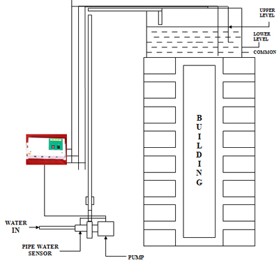 Used advanced embedded technology, 7.29921259098 7.29921259098 5.09842519165 in. WiFi connectivity would be an issue for certain homes and apartments. All the commercial products available on Amazon use a similar approach to detect water level. Manual/auto/off modes. This means, the input probes can be connected to the multiplexer channels and the Node MCU can read from them one after the other by altering the state of the multiplexer (think of it as three taps connected to the same pipe and we get to choose the one pipe that is open at any time). Free shipping on orders above Rs.499/- Dismiss, PiBOX India Raspberry Pi 4 8GB Jump Start8 Combo kit 4813W with Pi4 8GB, Pi4 Black case,16GB Noobs Card, BIS 3 amps Charger, Copper Heatsink, HDMI Cable, Ethernet Cable and Adapters 2022 Model, REES52 Ultrasonic Range Finder Module Sensor Distance Measuring Transducer New, PiBOX India Raspberry Pi 4 4GB Easy Cool 4 Combo kit 4413W with Pi4 4GB, Pi4 Fan case, Dual Speed Fan,16GB Noobs Card, BIS 3 Amps Charger, 3 Piece Heatsink, HDMI Cable and Accessories, Erratum Solutions FPM10A Fingerprint Reader-Sensor Module Arduino Locks. This unit will display the Water Level in percentage, Pump status, tank Height and Sump tank status.. Pure water is a bad conductor of electricity and impurities in water improve conductivity. Unlike the digital pin read which gives a login level HIGH or LOW based on a threshold, the analog pin provides a scaled value. I mainly work with printed circuit boards on proteus to bring life to my inventions. There is a current limiting resistor involved between transistor and LED and it prevents higher voltage to destroy the LED. This meant that the Mk1 design is not suitable for use in certain parts of the world and we had to go back to a new design. My colleague built a prototype with the Mk1 design and tested it at his home (in Trivandrum, Kerala). In view of this, Bluetooth module based Water Level Monitoring system is an innovative idea that will inform the users about the level of liquid and will prevent it from overflowing. LEDs will be monitoring the water level in the tank and the functionality of each LED is explained below : Presently, as the water ascends the sensors begin to get in contact with the water and the transistors are activated and there is a progression of current in the transistors making the LEDs light up. The Node MCU board can also be stripped down further and could be powered by a battery, but we did not venture in that direction as power supply was available on the terrace. Easy to install. I tested this prototype with packaged drinking water and the results were as expected. However, the Node MCU board has one Analog pin and this would limit the number of input probes and the detected water levels to just one. Digital pin D1 is set to output mode while pins D2, D5, D6, D7, D8 are set to input mode. Get an alert via email when the water level reaches a critical threshold. The analog pin read gave values between 265 to 300 indicating an input probe voltage of ~1V. Your personal data will be used to support your experience throughout this website, to manage access to your account, and for other purposes described in our privacy policy. Fundamentally, the unit is comprised of different sensors going about as a switch. Water level detection (or liquid level detection) is not a new problem and there are a number of commercial off-the-shelf products available in the market. To view or add a comment, sign in, Great write up Kishor, by the way great solve too.hope you can turn this to a commercial product, Awesome, man. Save electricity and easy installation and 12 months warranty +package contains:1 water level controller unit, 6 pic sensors probes (For upper and down tank), 1 user manual with all technical details, It can use with suitable up to 2hp motor and suitable for single phase mcb starter panel, submersible motors and jet pumps, It can use with overhead tank and under ground tanks or overhead tank only, Dry run protection. To resolve this type of problems by using implementation of water level monitors and control systems using wireless technology which will transmit the information to the smart phone and indicate the level of water in the overhead tanks.
We discussed about having a smart sensor hooked to a programmable switch that can turn on/off the motor. The HC-SR04 ultrasonic module is a module that can provide non-contact measurement within the range of 2cm to 400cm with ranging accuracy that can reach 3mm. The water in Trivandrum had less impurities and hence had a higher resistance. (A high resistance between GND and D4 grounds residual voltage without grounding the signal from P2). Manual mode: (motor pump will be constantly On). This project monitors the water level and emails alerts.
I decided to give this a shot and see if I can come up with a solution. If Water level below 20% then Pump will start Running and. We possibly need to make two channels so when they are in contact with water they will go about as a switch, as water is a good conductor of electricity. This idea can be extended further to replenish the sump if we add water level sensors to the sump as well.
A current limiting resistor (R1 - 440 ohms) is connected in series with the output pin D7 and probe P1 to limit the total current to ~11 milli amps (or lower). It works very long life. Stick the buzzer behind the PCB board and also fix the power supply by taking care of the transformer. Level Monitoring and Control with dry Pump run protection using Ultrasonic Sensor and Android Application via bluetooth HC-05. Most of these products use carbon/steel probes. #include // Include library used for measuring the distance using HC-SR 06 sonar sensor. Some of the alternatives that were considered and dropped: I built two boards with the Mk2 design and they are being tested by two colleagues at their respective houses.
if Pump running and Sump tank empty then Pump will stopped. Now, that weve collected all the components lets assemble them and design the circuit. Gap between Ultrasonic and Max water level adjusted in Arduino code. I selected the CD74HC4067 16 channel multiplexer (for it's relatively low cost and the reasonably good switching speed). When the water pump is started and the water level starts to rise, what actually happens is that every sensor gets activated one by one and finally, when the water level reaches the topmost sensor a buzzer is activated from the unit indicating that the tank is full and one needs to turn off the water pump hence, saving the electricity bill and as well as flow of water from the tank. When the P2 probe was dropped into the mug with water, the green LED lit up validating this design. After the HC-SR04 is triggered, it sends out eight 40Khz sound waves to the surface of the water. We will screw the two L hooks to the device and fix it into the wall and afterward take A/C 220V from any socket and give it to the board. Awesome project. Then cut the plastic board for the Power Switch. The second resistor (R2 - 22,000 ohms) acts as a pull down resistor and prevents input pin D4 from floating. On getting to the surface of the water, the wave is echoed back to the sensor and the arduino reads the echo pin to determine time spent between triggering and receiving of the echo. It observes the level of water and provides the information to the registered users through wireless. The Node MCU (and ESP8266) has an onboard 10-bit Analog to Digital Converter (ADC). Sump Water level sensor, which are dipped in to the Sump Water Tank or Use non-contact sensor for Pump suction line, And Analog pin present on the Arduino Nano will be used to sense the presence of water. This may not be ideal depending on the house/apartment. The Atmega 328p or similar micro controllers do not have built in WiFi, so, we decided to stick with the Node MCU and add a Multiplexer/Demultiplexer. If P4 is hung close to the top of the tank, the motor can be turned off once non-zero voltage is detected at P4. This video will illustrate the working principle of the Water Quality Monitoring and Notification System. The output pin would send 5V DC voltage into the probe and water and the input pin would read the voltage and would give back logic level HIGH (1) if the voltage is above (2.6V) a threshold value. This is a low cost board that comes with WiFi networking. This requires a person to check the water levels in the overhead tank and the sump at periodic intervals, turn on the motor when the water level drops down in the overhead tank and turn off the motor once the tank is filled. Level Monitoring and Control with dry Pump run protection using Ultrasonic Sensor and Android Applcation via bluetooth HC-05. This is probably one of the challenges every one of us faced at some point. In auto mode: ( auto motor on and auto off) . View the water integrity and level of selected areas on your Android phone by using an HC-06 Bluetooth module to make an irrigation system. The idea is to connect two probes to two digital pins of the Arduino, one set to output mode and the other to input mode. #define ECHO_PIN 7 // Arduino pin tied to echo pin on the ultrasonic sensor. During testing, the digital input pins always read logic level LOW (0) even when the probes were immersed in water. Another problem Ive observed is with the diaphragm getting water vapour settled on it causing accuracy problems. Keep rocking. One of the major problems faced by most of the countries is the issue of water scarcity in the world. We have to see how long the carbon electrodes work in real world scenario. I decided to build a microcontroller based solution that detects and transmits the water level to a cloud hosted database. Choose that place which is out of reach of children and from where you can easily turn ON and OFF the switch. This problem can be tackled in an electronic way. We could go with a micro controller like Atmega 328p (used on the Arduino board) that has multi-channel ADC (and hence multiple Analog pins) or use a multiplexer/demultiplexer with the Node MCU board. As P2 and P3 are immersed in water, we should get a non-zero voltage reading at P2 and P3, and zero voltage at P4. A decent and very cheap office entrance door alarm system to keep track of every person's entry or departure. I choose ESP8266 based Node MCU microcontroller board. Yet another very useful utility for day to day life. This would be too low for the digital pin to give a logic level HIGH and that explains the failure of the older design in Trivandrum. As a first step I built a prototype to validate this idea with an Arduino Nano. percentage=(ActualReading/WaterLevelMAX*100); else if(percentage>20 && percentage<=100), if(percentage>20 && percentage<=100 && flag ==1), else if(percentage>20 && percentage<=100 && flag ==0), https://drive.google.com/file/d/11egiPu2fzW4Sn2ypX6yYpG9r5-iuY-TP/view?usp=sharing, https://drive.google.com/file/d/1_5t3tVkQNHQk60k0gRRFQR1lUCjvaC1z/view?usp=sharing. There is a need to control the water wastage to save the environment and water resources. And also to design a contactless water level indicator and controller using ultrasonic sensor with DRY PUMP RUN PROTECTION.
#define MAX_DISTANCE 500 // Maximum sensor distance is rated at 400-500cm. Ive tackled it in a slightly different way sometime back, using an ultrasonic sensor. The water level monitoring system is a automatic process to detect and indicate the level of water in the reservoirs, overhead tank or any other storage containers, etc. But it is a slightly better than electrodes corroding under water. Subsequently the Mk2 prototype was tested in Trivandrum and was able to detect water level without the need for mixing salt. Since we know that the speed of sound is around 340m/s then we can calculate the distance using; To determine the level of the water in the tank we must know the total length of the tank. In the tank, there is a set of sensors and they act like a switch. These days everyone has an overhead tank at their homes. Once salt was added to water, the conductivity would go up (and resistance would down) and the voltage drop was not significant. Once the design was validated with an Arduino board, the next step was to use a board with WiFi capability and send the water levels to a cloud hosted database. A more elegant solution that provides a programming interface would let the end user build different solutions of his/her choice. The digital pins on the Node MCU board output 3.3V DC and hence a 330 Ohm current limiting resistor (R1) was used instead of the 440 Ohms used with the Arduino Nano board. This can further used if you wish to replace the water tank with a new one. http://xtel.in/water-level-monitor-using-sr04-and-labview.html. A few months back I had a discussion with a colleague about the need for a water level sensor for his house. Used advanced embedded technology, 7.29921259098 7.29921259098 5.09842519165 in. WiFi connectivity would be an issue for certain homes and apartments. All the commercial products available on Amazon use a similar approach to detect water level. Manual/auto/off modes. This means, the input probes can be connected to the multiplexer channels and the Node MCU can read from them one after the other by altering the state of the multiplexer (think of it as three taps connected to the same pipe and we get to choose the one pipe that is open at any time). Free shipping on orders above Rs.499/- Dismiss, PiBOX India Raspberry Pi 4 8GB Jump Start8 Combo kit 4813W with Pi4 8GB, Pi4 Black case,16GB Noobs Card, BIS 3 amps Charger, Copper Heatsink, HDMI Cable, Ethernet Cable and Adapters 2022 Model, REES52 Ultrasonic Range Finder Module Sensor Distance Measuring Transducer New, PiBOX India Raspberry Pi 4 4GB Easy Cool 4 Combo kit 4413W with Pi4 4GB, Pi4 Fan case, Dual Speed Fan,16GB Noobs Card, BIS 3 Amps Charger, 3 Piece Heatsink, HDMI Cable and Accessories, Erratum Solutions FPM10A Fingerprint Reader-Sensor Module Arduino Locks. This unit will display the Water Level in percentage, Pump status, tank Height and Sump tank status.. Pure water is a bad conductor of electricity and impurities in water improve conductivity. Unlike the digital pin read which gives a login level HIGH or LOW based on a threshold, the analog pin provides a scaled value. I mainly work with printed circuit boards on proteus to bring life to my inventions. There is a current limiting resistor involved between transistor and LED and it prevents higher voltage to destroy the LED. This meant that the Mk1 design is not suitable for use in certain parts of the world and we had to go back to a new design. My colleague built a prototype with the Mk1 design and tested it at his home (in Trivandrum, Kerala). In view of this, Bluetooth module based Water Level Monitoring system is an innovative idea that will inform the users about the level of liquid and will prevent it from overflowing. LEDs will be monitoring the water level in the tank and the functionality of each LED is explained below : Presently, as the water ascends the sensors begin to get in contact with the water and the transistors are activated and there is a progression of current in the transistors making the LEDs light up. The Node MCU board can also be stripped down further and could be powered by a battery, but we did not venture in that direction as power supply was available on the terrace. Easy to install. I tested this prototype with packaged drinking water and the results were as expected. However, the Node MCU board has one Analog pin and this would limit the number of input probes and the detected water levels to just one. Digital pin D1 is set to output mode while pins D2, D5, D6, D7, D8 are set to input mode. Get an alert via email when the water level reaches a critical threshold. The analog pin read gave values between 265 to 300 indicating an input probe voltage of ~1V. Your personal data will be used to support your experience throughout this website, to manage access to your account, and for other purposes described in our privacy policy. Fundamentally, the unit is comprised of different sensors going about as a switch. Water level detection (or liquid level detection) is not a new problem and there are a number of commercial off-the-shelf products available in the market. To view or add a comment, sign in, Great write up Kishor, by the way great solve too.hope you can turn this to a commercial product, Awesome, man. Save electricity and easy installation and 12 months warranty +package contains:1 water level controller unit, 6 pic sensors probes (For upper and down tank), 1 user manual with all technical details, It can use with suitable up to 2hp motor and suitable for single phase mcb starter panel, submersible motors and jet pumps, It can use with overhead tank and under ground tanks or overhead tank only, Dry run protection. To resolve this type of problems by using implementation of water level monitors and control systems using wireless technology which will transmit the information to the smart phone and indicate the level of water in the overhead tanks. We discussed about having a smart sensor hooked to a programmable switch that can turn on/off the motor. The HC-SR04 ultrasonic module is a module that can provide non-contact measurement within the range of 2cm to 400cm with ranging accuracy that can reach 3mm. The water in Trivandrum had less impurities and hence had a higher resistance. (A high resistance between GND and D4 grounds residual voltage without grounding the signal from P2). Manual mode: (motor pump will be constantly On). This project monitors the water level and emails alerts.
I decided to give this a shot and see if I can come up with a solution. If Water level below 20% then Pump will start Running and. We possibly need to make two channels so when they are in contact with water they will go about as a switch, as water is a good conductor of electricity. This idea can be extended further to replenish the sump if we add water level sensors to the sump as well.
A current limiting resistor (R1 - 440 ohms) is connected in series with the output pin D7 and probe P1 to limit the total current to ~11 milli amps (or lower). It works very long life. Stick the buzzer behind the PCB board and also fix the power supply by taking care of the transformer. Level Monitoring and Control with dry Pump run protection using Ultrasonic Sensor and Android Application via bluetooth HC-05. Most of these products use carbon/steel probes. #include