The first step is to "normalise" the incoming data. . The sketch can then recognise the utterances without being connected to a PC.
The program calculates the mean and S.D. The number is difference ("distance") between the utterance and and that template. All that takes around 100uS. I have a friend who has messed with Linux before, and he agreed that SOPARE is a good system. However, the program was hacked around a lot as I tried various methods of analysis so it's not neccessarily easy to follow. The diagram above shows a typical filter. Recompile those sketches so that they perform bandpass filtering on the Arduino. The utterance is assumed to start when a the total energy in the bands exceeds a threshold. Click the File|Open menu item and load the Train2raw.txt file. My first thoughts were to use some sort of statistical technique like principal component analysis, factor analysis, cluster analysis, etc. With higher gains, background noise is amplified too much; when there was speech, the AGC reduced the speech signal to reasonable level but when you stopped speaking, the noise slowly returned.
I'll call them "bands" even though ZCR is not really a frequency band. SpeechRecog1.exe makes the band filters "equally spaced" on a logarithmic scale. It was fun, but I didn't have a real computer to learn C with, and I only recently got my arduino back out to try to learn how to use it as well. The Arduino sends sample utterances to a PC and the PC calculates the utterance templates. I used the 3.3V output of the Nano as the analogue reference voltage so 0 to 1023 means 0V to 3.3V. Most groups had a PDP-8 or PDP-11. A template is a typical example of an utterance. You could connect the module directly to one of the ADC input pins but in the diagram above I have included a simple RC high-pass filter.
An Arduino Nano doesn't have sufficient computing power to calculate a Fourier transform as the samples arrive. For a bandpass filter, Q= fcenter/ (fmax - fmin). It's been hacked and modified so much it's not really readable. Q is the "Q-factor" which is 1 / (the width of the band). I don't think you'd need to do this and you could just say it upfront in the readme that there is no support.
If the bands are far apart, you don't want Q so big there are gaps between them. Click the Utterances|Recognise|RecogniseAll menu item to compare each of the test examples with each template. Or what about a remote-control robot? How does a Nano compare with back then? The mean amplitude of the whole utterance is measured so that the data can be normalised. So "importance" is 1/ (50+standard deviation). To me, that makes sense. As a result, we're limited to maybe a dozen arithmetc operations per sample. If the output depends only on the previous input values then it is called a Finite Impulse Response filter: "FIR" (b0 and b1 are set to zero in the above diagram). The the overall difference is.
How? :) I wish I had time to play with it but at least now it's out there easy to find for anyone interested. Please let me know how you get on. The SpeechRecog1.exe Windows program calculates digital filter coefficients. Formant tracking watches how the frequencies of those peaks change during the utterance. The sketch can send the values to the PC over the serial line but serial transmission slows it down to around 1100sps (at 57600baud).  The result is a 16-bit int centred on 0.
The Gain is connected to VDD which is the lowest gain. It's just an easy way to make the code public in a way that allows everyone to see who picks up your code and does what to it - rather than everyone working in their own silo and potentially re-doing the same thing others already did.I would not mind doing something with that, but the time is extremely limited. It's hard to find a definitive value for how fast a Nano can perform addition and multiplication. After you have recompiled the speechrecog1.ino sketch, it gets sample utterances and sends them to the PC so the PC can calculate the "templates". For instance the "th" part of "three" is quite variable compared with the "ee" part. Usually, when you click on a grid square, the utterance is recognised on the PC. If you want to have fun and learn, why don't you start immediately? Each of the examples is shifted to the left or right until it best matches the template for that utterance. It does some terrifying things to you. And 32-bit addition or multiplication takes around 5 times the single-byte time. Neither worked well for me. A more appropriate way of dividing the data into bands is by using digital filters. I did some research on speaker recognition back in the 90's and I used an old (really old) edition of Transactions of the IEEE much like you did. What is (objectively) the best voice recognition system for the arduino. It depends on how you measure it: do you include fetching and storing the values for instance. of the row of the grid is displayed. It's nothing special, you will find lots of others if you search the web.
The SpeechRecog1.exe Windows program available on Github calculates coefficients and exports them as a Coeffs.h file. The utterance starts when the total energy in a band exceeds a threshold. A MAX9814 includes a microphone amplifier and an AGC (Automatic Gain Control). It's not a difficult algorithm.Peter. In the image above, the frequency axis (x-axis) is linear.  and I am mainly concerned about the byte size that the system can hold. I must have bought it years ago. So we subtract the running mean of the incoming value from val. The Arduino ADC has 10 bits so the numeric value goes from 0 to 1023. In the Utterances|Recognise sub-menu, check the OnArduino menu item. (Or just copy-and-paste them into the source.).
I'm assume you already know how to program an Arduino - if not there are lots of Instructables tutorials. The list of utterances doesn't have to match the training set - you could add some "incorrect" words. So I reckon we're stuck with using a few digital filters.  We're trying to make each training example best fit its template. ), I just want a system for telling the robot to light an LED or move forward 12 units. The speechrecog0.ino sketch tests the ADC.
1 year ago, I'm happy to give the source away. The most popular way of filtering the data is by performing a Fourier transform on the input to obtain its spectrum. With only 4 frequency bands, we can't hope to calculate formant frequencies but they will affect the energy in the different bands. are previous values. A "three" often looked like a "seven" and a "four" looked like a "zero". on Step 12. The lowest distance is the best and that one is displayed in the grid as the best match. I think I will use SOPARE on a raspberry Pi for this. What sort of accuracy were you getting? We can deal with this problem either by using "One-versus-All" where one class is compared all the other classes combined or by using "One-versus-One" where every pair of classes is compared. In C we would calculate it as: where x[n] is an input sample value and y[n] is an output value. The results are not quite as good but should be over 90% correct. Hi Peter,Thanks for your awesome instructable - not only a very interesting topicbut also extremely well explained and described.Would you consider putting your sources on github?
If you don't mind - just add it to the github repo maybe?This looks like a pretty cool instructable. Other speech recognition projects exist but either require a web connection and that you send all your private conversations to Amazon or Google; or they require a larger computer like a Raspberry Pi. How to Make VOICE CONTROLLED Car by using ARDUINO | Indian Lifehacker, IoT ESP8266 Arduino Tutorial : Voice Control LED Over Wi-Fi with an iOS 11 Swift 4 App, Arduino Tutorial Arduino control arduino voice recognition with Android voice command via Bluetooth, How to Make Voice Control Home Automation System using Arduino | Voice Control DIY, How to Control LED Using Your Voice Command Arduino | Voice Control Arduino, Arduino Tutorial 23: Arduino control with Android voice command (via Bluetooth), How to make voice controlled robot using Arduino and android application, How to Talk with Arduino Board | Voice Recognition Module | Mert Arduino and Tech, Akulva animatronic speech demo using Arduino, Picotalk and servos, Obstacle Avoiding Arduino Robot with Voice Control Tutorial, Tutorial Android Voice Recognition Arduino #2, [ Arduino Day 2017 ] 9 Demo: Turning light on/off using voice command, Voice Activated Arduino Demo using smartphone, How to make voice control home automation system using arduino, How To #1. That way thoseof us inclined to work the code further can just fork your repo, butothers would be always able to go back to your original code. That's particularly true when you're using integer arithmetic as we'll be doing on the Nano. We can ignore a1 as it is zero. You could add the Talkie library to provide feedback of the word that has been recognised. The coefficients can be calculated on a PC but the actual filter itself runs on the Arduino using integer arithmetic. I doubt if it would be plug-and-play for the form design files (*.DFM - I've not tried it). As far as I can see, all modern speech recognition starts with either a Fourier transform possibly followed by cepstral analysis or they use LPC coefficients. 
I don't want to have to remove the arduino completely though, since I don't know Python scripting and am still learning C programming (I do know BASIC though!).  Another group had re-purposed a Univac missile fire control system running at 1MIPS. Click the Utterances|Recognise|RecogniseAll menu item to compare each of the training examples with each template. Answer Now, when you click on a grid square, the utterance is sent to the Arduino; the sketch there does the recognition and sends the result back to the PC. It basically identifies the words and then checks the order to see what the response should be. The Kendryte K210 chip has hardware FFT. Of course, there are big individual differences. In speech recognition, it's common to apply "Dynamic Time Warping" to recorded utterances.
When you read ADCL, the value in ADCH is frozen until you read it too. Did you make this project? Now click the "Test Templates" tab. The Arduino library has put the ADC into single conversion mode so we need to set ADSC to start each conversion. Once the 13 segments have been stored, we have to choose which of our sample words we think those 65 numbers most resembles.  How would you like to be able to proceed? Thanks a lot. Hi Peter,A bit late to reply, sorry about that. You may want to calculate the bands in other positions. If so do post it. We would prefer to be doing other things while the ADC is waiting for the conversion so I do it differently. I found a gain of 40dB gave the best signal-to-noise ratio with the microphone on a boom near my mouth. It would then try to recognise the words that you say and dial that number. Just have ten "templates" for the ten different digits and measure the difference between the incoming data and each of the templates. I chose the MAX9814 microphone amplifier as it has automatic gain control.
 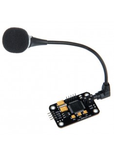 It's easier to get the maths wrong for an IIR filter so that he output goes crazy or gets stuck.
The Gain pin controls the gain of the AGC: In the circuit shown above, I have left A/R unconnected. It initialises the ADC and chooses the correct input pin. With a biquad filter, if Q is too large, the filter becomes unstable. I could MAYBE use multiple, but they aren't cheap. Personally, I don't see that's useful for single word: you might as well just recognise the whole thing.  After you have recorded all the sample utterances, the grid will be full. DIY, Wireless, Modular, Arduino, 3D Printed! Copy the Templates.h file into the same directory as the speechrecog2.ino sketch. After 13 segments of data have been stored, the resulting 65 numbers are sent to the PC. That will load some utterances with which to test the templates. Click the Utterances|RecordTraining menu item to start recording utterances. It can collect samples at around 9ksps. An utterance starts when the amplitude exceeds a threshold. > const int AUDIO_IN = A7;> Should I change itYes. It means that the lower frequencies of speech (below 1.4kHz) are de-emphasised. The SpeechRecog1.exe Windows program you used to calculate the coefficients can also be used to calculate the templates.
  If Instructables hasn't mangled them they should be good enough for OCR. x[n-1], y[n-2], etc. Click on a cell in the grid to display the utterance; the horzontal axis is time and the vertical axis is the amplitude of each band. In other words, the 10 templates now contain the average of the data. You can click on any of the cells and the segments for that example will be displayed. I could admit defeat and use a phone, but that takes way too much of the fun out of making it.
If the system shall recognize multiple speakers, add enough memory for each one.
But you might have more success with them. Question 6 months ago. A formant is a peak in the energy of the spectrum and a vowel is recognised by the relative sizes and frequencies of the first two or three formants. The higher the order the more control you have over the filter's response curve. The segments can be shifted left or right to improve the fit. Just stay sober when you want to use the robot. Arduino Robotic Arm Controlled by Touch Interface. When you click on a cell to display the utterance, it is compared with the template for all the rows (i.e.
So the first stage is to pass the input through different bandpass filters. Firstly use SpeechRecog1.exe to calculate the coefficients for the digital filters as described in Step 6. Then it starts the conversion and waits until the conversion is complete.
Also, I don't speak Delphi so if I were to work on that, I would probably port it to something else (maybe Python) that runs on non-Windows platforms as well and does not require proprietary environments.
Type strings for those utterances into the memo at the left of the window. It is certainly not "low noise" and its output can only get within 1.5V of Vcc. I add a fifth "band" for the Zero Crossing Rate - the "ZCR". Here is an online filter calculator. Clearly, a Nano isn't going to be as good as those. I got voice and speech recognition confused. You can have nearly as much fun making something that understands "LED", "ON", MOVE", "ONE", TWO", "THREE", etc. You could connect them to digital pins of the Arduino so you can control them in software: for "unconnected", set the pin to input. It would be great if you worked on it further. For our signal processing, we want it centred around 0. The "process the sample" code is executed while the next ADC conversion is happening. The Arduino sends the segment data to the program. Introduction to voice recognition with elechouse v3 and arduino. Maybe you can use your mobile phone to connect to one of those services to do the interpretation for you, then send the commands to the Arduino. I will need to find a way for an arduino and a Raspberry Pi to communicate. A digital filter performs some sort of simple maths on the previous N input samples and maybe the previous N filter-output samples to calculate the next output value of the filter. It's been a while since I worked in Delphi/Pascal - but I still think it will help. The results are shown in the right-hand memo.
Clearly, the higher the order the more coeficients you need and the more maths you have to do per sample. Any chance to release the source of the exe? We can't afford more than a second order IIR filter. So the templates need to be tidied up a little. Powered by Discourse, best viewed with JavaScript enabled. Clearly the trick for any digital filter is finding the right coefficient values. 2 segments.
That's a work-alike freeware version of Delphi4. I think I could use the EasyVR Shield, but it only holds 32 triggers. 8-bit addition takes 0.4 to 0.9 uS. My recogniser algorithm on the PC is not used at all.
Because the module is AC-coupled, two resistors are used to centre the ADC input around 1.65V. In Setup() I use the standard Arduino library code to initialise the ADC: The reference voltage for the ADC is set to the ARef pin and ARef is connected to the 3.3V pin. In the main loop, to start a conversion we set the ADSC bit (ADC Start Conversion). Or do you mean the Arduino code. Could an Arduino Nano do the same as a computer from that era? HMMs treat the sound as a sequence of states. This tells ADC to start the conversion. Several bandpass IIR digital filters divide the signal into frequency bands.