I need some help understanding the sizing orifice bore in cavitating flow and thick orifice in cavitating flow. The orifice meter is recommended for clean and dirty liquids and some slurry services. 0000044111 00000 n
0000052062 00000 n
Orifice diameter (dO) shall be calculated by equation (13) using assumed upstream pressure. 0000060195 00000 n
Law of conservation of mass will apply. Downstream of the Vena Contracta in the recovery zone, the fluid decelerates converting excess kinetic energy into pressure as it slows. All flow calibrated components are measured on instruments that are calibrated with Lenox Laser traceable standards. (3) The calculated hole diameter of RO should be rounded to the conservative size for easy manufacturing.  ), ( Thanks for posting.I have started using RW Miller flow consultant. Also, is this a dimensionless equation? orifice calculator : Pipe center to orifice center length (m). A discharge coefficient cd = 0.975 can be indicated as standard, but the value varies noticeably at low values of the Reynolds number. The Orifice plate is a very robust flow measurement device. All Rights Reserved. Since it depends on the orifice and pipe diameters (as well as the Reynolds Number), one will often find Cf tabulated versus the ratio of orifice diameter to inlet diameter, sometimes defined as b. Cookies are only used in the browser to improve user experience. 0000062332 00000 n
if(typeof ez_ad_units!='undefined'){ez_ad_units.push([[300,250],'whatispiping_com-banner-2','ezslot_8',851,'0','0'])};if(typeof __ez_fad_cmd!='undefined'){__ez_fad_cmd.push('div-gpt-ad-whatispiping_com-banner-2-0');}else{__ez_fad_cmd=['div-gpt-ad-whatispiping_com-banner-2-0'];};report this ad, Guidelines for sizing of Restriction Orifice for single-phase fluids (With PDF). American Society of Mechanical Engineers (ASME). orifice dimensions simple Orifice diameter (dO) shall be calculated by equation (13). ), ( endstream
endobj
10 0 obj<>>>/Filter/Standard/O($/DZ%@{6m7)/P -3392/R 4/U(FaGk" )/V 4/EncryptMetadata false/StrF/StdCF/StmF/StdCF>>
endobj
11 0 obj<>
endobj
12 0 obj<>/MediaBox[0 0 612 792]/Resources 13 0 R/Type/Page>>
endobj
13 0 obj<>
endobj
14 0 obj<>
endobj
15 0 obj<>stream
For more information on how we calculate flow rate and orifice diameter click here, 12530 Manor Rd.Glen Arm, MD 210571 (800) 49-HOLES (46537)(410) 592-53001 (410) 592-3362 (Fax).
), ( Thanks for posting.I have started using RW Miller flow consultant. Also, is this a dimensionless equation? orifice calculator : Pipe center to orifice center length (m). A discharge coefficient cd = 0.975 can be indicated as standard, but the value varies noticeably at low values of the Reynolds number. The Orifice plate is a very robust flow measurement device. All Rights Reserved. Since it depends on the orifice and pipe diameters (as well as the Reynolds Number), one will often find Cf tabulated versus the ratio of orifice diameter to inlet diameter, sometimes defined as b. Cookies are only used in the browser to improve user experience. 0000062332 00000 n
if(typeof ez_ad_units!='undefined'){ez_ad_units.push([[300,250],'whatispiping_com-banner-2','ezslot_8',851,'0','0'])};if(typeof __ez_fad_cmd!='undefined'){__ez_fad_cmd.push('div-gpt-ad-whatispiping_com-banner-2-0');}else{__ez_fad_cmd=['div-gpt-ad-whatispiping_com-banner-2-0'];};report this ad, Guidelines for sizing of Restriction Orifice for single-phase fluids (With PDF). American Society of Mechanical Engineers (ASME). orifice dimensions simple Orifice diameter (dO) shall be calculated by equation (13). ), ( endstream
endobj
10 0 obj<>>>/Filter/Standard/O($/DZ%@{6m7)/P -3392/R 4/U(FaGk" )/V 4/EncryptMetadata false/StrF/StdCF/StmF/StdCF>>
endobj
11 0 obj<>
endobj
12 0 obj<>/MediaBox[0 0 612 792]/Resources 13 0 R/Type/Page>>
endobj
13 0 obj<>
endobj
14 0 obj<>
endobj
15 0 obj<>stream
For more information on how we calculate flow rate and orifice diameter click here, 12530 Manor Rd.Glen Arm, MD 210571 (800) 49-HOLES (46537)(410) 592-53001 (410) 592-3362 (Fax).
If you only know the pressure drop through the orifice for one flow rate then you may be able to approximate the orifice performance with a component that is set to a specific Cv or Kv value. %%EOF International Standards Organistion method as described in ISO 5167-2: \displaystyle Y = 1 - \left(0.351 + 0.256 \beta^{4} + 0.93 \beta^{8} \right) \left( 1 - \left(\frac{P_{s,2}}{P_{s,1}}\right)^{1/k} \right), Calculation of Flow through Nozzles and Orifices, discharge coefficients for nozzles and orifices, Flow Measurement Engineering Handbook, R. W. Miller, Albright's Chemical Engineering Handbook, L. Albright, Instrument Engineers' Handbook, Vol. C_{d}characterises the relationship between flow rate and pressure loss based on the geometry of a nozzle or orifice. Calculate cavitation index, Kd, using Equation (15), and compare with minimum allowable value. Measurement of fluid flow by means of pressure differential devices, Part 1: Orifice plates, nozzles, and Venturi tubes inserted in circular cross-section conduits running full. \beta, the ratio of orifice to pipe diameter which is defined as: \displaystyle \beta = \frac{D_{o}}{D_{1}}.
 Combining (1) and (2), assuming A2 < A1, gives the "ideal" equation: q = A2 [ 2(p1 - p2) / (1 - (A2 / A1)2) ]1/2 (3). I have few queries.On what basis the deflection ratio for eccentric orifice is achieved?What is the out put from that deflection ratio? Semiconductors, medical equipment, lasers, optics and aviation and aerospace. 12 ), ( International Organization of Standards - ISO 5167-1:2003 Measurement of fluid flow by means of pressure differential devices, Part 1: Orifice plates, nozzles, and Venturi tubes inserted in circular cross-section conduits running full. 0000001926 00000 n
It is recommended that location 1 be positioned one pipe diameter upstream of the orifice, and location 2 be positioned one-half pipe diameter downstream of the orifice. Currently using 4mm orifice in a system to produce a flow of 760m3/h.The 4mm orifice is prone to fouling and clogging alot. orifice pendahuluan McNally Institute: Approximate Flow through an Orifice, Pipe Flow Calculations: Office Plate Sizing and Flow Rate Calculator. 1 Welcome to my space, I am Anup Kumar Dey, an experienced piping engineer for the last 19 years. 15 Divide the flow of the liquid by the velocity of the liquid to determine the area of the orifice in square feet. American Society of Mechanical Engineers (ASME). Currently, I work in a reputed MNC as a Senior Piping Stress Engineer. (The default calculation involves air passing through a medium-sized orifice in a 4" pipe,
Types and Applications of Concrete Pipes (PDF). The pressure recovery is limited for an orifice plate and the permanent pressure loss depends primarily on the area ratio. calculator orifice reynolds plate number diameter fluid velocity rho density where
Combining (1) and (2), assuming A2 < A1, gives the "ideal" equation: q = A2 [ 2(p1 - p2) / (1 - (A2 / A1)2) ]1/2 (3). I have few queries.On what basis the deflection ratio for eccentric orifice is achieved?What is the out put from that deflection ratio? Semiconductors, medical equipment, lasers, optics and aviation and aerospace. 12 ), ( International Organization of Standards - ISO 5167-1:2003 Measurement of fluid flow by means of pressure differential devices, Part 1: Orifice plates, nozzles, and Venturi tubes inserted in circular cross-section conduits running full. 0000001926 00000 n
It is recommended that location 1 be positioned one pipe diameter upstream of the orifice, and location 2 be positioned one-half pipe diameter downstream of the orifice. Currently using 4mm orifice in a system to produce a flow of 760m3/h.The 4mm orifice is prone to fouling and clogging alot. orifice pendahuluan McNally Institute: Approximate Flow through an Orifice, Pipe Flow Calculations: Office Plate Sizing and Flow Rate Calculator. 1 Welcome to my space, I am Anup Kumar Dey, an experienced piping engineer for the last 19 years. 15 Divide the flow of the liquid by the velocity of the liquid to determine the area of the orifice in square feet. American Society of Mechanical Engineers (ASME). Currently, I work in a reputed MNC as a Senior Piping Stress Engineer. (The default calculation involves air passing through a medium-sized orifice in a 4" pipe,
Types and Applications of Concrete Pipes (PDF). The pressure recovery is limited for an orifice plate and the permanent pressure loss depends primarily on the area ratio. calculator orifice reynolds plate number diameter fluid velocity rho density where
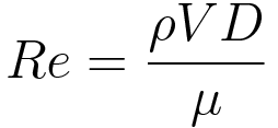
22 The equation can be adapted to vertical flow by adding elevation heights: p1 + 1/2 v12 + h1 = p2 + 1/2 v22 + h2 (1b), = specific weight of fluid (kg/m3, slugs/ft3), Assuming uniform velocity profiles in the upstream and downstream flow - the Continuity Equation can be expressed as, q = v1 A1 = v2 A2 (2). Since the actual flow profile at location 2 downstream of the orifice is quite complex, thereby making the effective value of A2 uncertain, the following substitution introducing a flow coefficient Cf is made. keep it up.. VYAY KRUTE VARDHTE EVANM NITAYM VIDHYA DHANAM SARVA DHANAM PRADHANAM More you spend more it will be that is Knowledge.. The coefficient of a meter depends on the position of the taps. startxref 0000028558 00000 n Whitehouse studied English literature and psychology at Queen's University, and book and magazine publishing at Centennial College. Pipe (inlet) diameter upstream of orifice. This is critical for any successful calculation otherwise significant errors will results and the whole procedure is useless. You can target the Engineering ToolBox by using AdWords Managed Placements. 0000001875 00000 n Very good writeup but it appears Equation 15 to calculate Kd is not defined. f_ac)ZQh7~[k2Ic3. Please provide me in detail information regarding above as I am working on same research area. Assume upstream pressure of the first stage orifice.
When the fluid has decelerated and returned to the normal bulk flow pattern the final downstream pressure has been reached. If the cavitation index equals to or slightly bigger than 0.37 (or 0.93), the design of the first stage RO is completed and go to step . Alternatively, please use our Flow Rate Calculator to determine the correct part based on the desired flow rate. If you have not yet determined the orifice size then to estimate this we would suggest that you temporarily use a Flow Control Valve in your system to control the flow rate in the pipe (to whatever flow rate you require). flow through precision sharp gas orifices The text is good as well as the formulas but in order to be useful, each parameters has to be defined and the unit in which it has to be used defined.
orifice calculation coefficient singularity Powered by, ( Reference number: ISO 5167-1:2003. International Organization of Standards (ISO 5167-1) Amendment 1. These applications will - due to browser restrictions - send data between your browser and our server. 7 0000001096 00000 n 0000063002 00000 n
(A) Critical flow (sonic region)- When the ratio of downstream pressure to upstream pressure, r4, is smaller than or equal to critical pressure ratio, rc, the following equation of orifice diameter for a critical flow should be used. The relationships for flow rate, pressure loss and head loss through orifices and nozzles are presented in the subsequent section. 0000051493 00000 n Thank you for posting this. Hello,Really useful text. The viscous effect is usually expressed in terms of the non-dimensional parameter Reynolds Number - Re. The deflection ratio of the eccentric orifice e is 0.75. Towers, turbines, gearboxes; processes for shaping and finishing component parts. Add standard and customized parametric components - like flange beams, lumbers, piping, stairs and more - to your Sketchup model with the Engineering ToolBox - SketchUp Extension - enabled for use with the amazing, fun and free SketchUp Make and SketchUp Pro .Add the Engineering ToolBox extension to your SketchUp from the SketchUp Pro Sketchup Extension Warehouse! Nozzles and orifices are often used to deliberately reduce pressure, restrict flow or to measure flow rate. ), ( The diameter ratio can be calculated to. How a Current to Pressure Transducer Works, Common Symbols Used in Process and Instrumentation Diagrams, How to Measure Electric Motor Insulation Resistance, How to Test 3-phase AC Motor Windings with an Ohmeter, How to Read Torque Speed Characteristics of AC Motors, Instrument Abbreviations Used in Instrumentation Diagrams, How to Convert Thermocouple Milivolts to Temperature, Principles & Formulas for Flow Measurement. The pressure recovery is much better for the venturi meter than for the orifice plate. Nozzles used for determining fluid's flowrate through pipes can be in three different types: The pressure difference dp = p1 - p2 between upstream and downstream is 100 kPa (1 105 N/m2).
), ( Thanks for posting.I have started using RW Miller flow consultant. Also, is this a dimensionless equation? orifice calculator : Pipe center to orifice center length (m). A discharge coefficient cd = 0.975 can be indicated as standard, but the value varies noticeably at low values of the Reynolds number. The Orifice plate is a very robust flow measurement device. All Rights Reserved. Since it depends on the orifice and pipe diameters (as well as the Reynolds Number), one will often find Cf tabulated versus the ratio of orifice diameter to inlet diameter, sometimes defined as b. Cookies are only used in the browser to improve user experience. 0000062332 00000 n
if(typeof ez_ad_units!='undefined'){ez_ad_units.push([[300,250],'whatispiping_com-banner-2','ezslot_8',851,'0','0'])};if(typeof __ez_fad_cmd!='undefined'){__ez_fad_cmd.push('div-gpt-ad-whatispiping_com-banner-2-0');}else{__ez_fad_cmd=['div-gpt-ad-whatispiping_com-banner-2-0'];};report this ad, Guidelines for sizing of Restriction Orifice for single-phase fluids (With PDF). American Society of Mechanical Engineers (ASME). orifice dimensions simple Orifice diameter (dO) shall be calculated by equation (13). ), ( endstream
endobj
10 0 obj<>>>/Filter/Standard/O($/DZ%@{6m7)/P -3392/R 4/U(FaGk" )/V 4/EncryptMetadata false/StrF/StdCF/StmF/StdCF>>
endobj
11 0 obj<>
endobj
12 0 obj<>/MediaBox[0 0 612 792]/Resources 13 0 R/Type/Page>>
endobj
13 0 obj<>
endobj
14 0 obj<>
endobj
15 0 obj<>stream
For more information on how we calculate flow rate and orifice diameter click here, 12530 Manor Rd.Glen Arm, MD 210571 (800) 49-HOLES (46537)(410) 592-53001 (410) 592-3362 (Fax). 
If you only know the pressure drop through the orifice for one flow rate then you may be able to approximate the orifice performance with a component that is set to a specific Cv or Kv value. %%EOF International Standards Organistion method as described in ISO 5167-2: \displaystyle Y = 1 - \left(0.351 + 0.256 \beta^{4} + 0.93 \beta^{8} \right) \left( 1 - \left(\frac{P_{s,2}}{P_{s,1}}\right)^{1/k} \right), Calculation of Flow through Nozzles and Orifices, discharge coefficients for nozzles and orifices, Flow Measurement Engineering Handbook, R. W. Miller, Albright's Chemical Engineering Handbook, L. Albright, Instrument Engineers' Handbook, Vol. C_{d}characterises the relationship between flow rate and pressure loss based on the geometry of a nozzle or orifice. Calculate cavitation index, Kd, using Equation (15), and compare with minimum allowable value. Measurement of fluid flow by means of pressure differential devices, Part 1: Orifice plates, nozzles, and Venturi tubes inserted in circular cross-section conduits running full. \beta, the ratio of orifice to pipe diameter which is defined as: \displaystyle \beta = \frac{D_{o}}{D_{1}}.
Combining (1) and (2), assuming A2 < A1, gives the "ideal" equation: q = A2 [ 2(p1 - p2) / (1 - (A2 / A1)2) ]1/2 (3). I have few queries.On what basis the deflection ratio for eccentric orifice is achieved?What is the out put from that deflection ratio? Semiconductors, medical equipment, lasers, optics and aviation and aerospace. 12 ), ( International Organization of Standards - ISO 5167-1:2003 Measurement of fluid flow by means of pressure differential devices, Part 1: Orifice plates, nozzles, and Venturi tubes inserted in circular cross-section conduits running full. 0000001926 00000 n
It is recommended that location 1 be positioned one pipe diameter upstream of the orifice, and location 2 be positioned one-half pipe diameter downstream of the orifice. Currently using 4mm orifice in a system to produce a flow of 760m3/h.The 4mm orifice is prone to fouling and clogging alot. orifice pendahuluan McNally Institute: Approximate Flow through an Orifice, Pipe Flow Calculations: Office Plate Sizing and Flow Rate Calculator. 1 Welcome to my space, I am Anup Kumar Dey, an experienced piping engineer for the last 19 years. 15 Divide the flow of the liquid by the velocity of the liquid to determine the area of the orifice in square feet. American Society of Mechanical Engineers (ASME). Currently, I work in a reputed MNC as a Senior Piping Stress Engineer. (The default calculation involves air passing through a medium-sized orifice in a 4" pipe,
Types and Applications of Concrete Pipes (PDF). The pressure recovery is limited for an orifice plate and the permanent pressure loss depends primarily on the area ratio. calculator orifice reynolds plate number diameter fluid velocity rho density where 
22 The equation can be adapted to vertical flow by adding elevation heights: p1 + 1/2 v12 + h1 = p2 + 1/2 v22 + h2 (1b), = specific weight of fluid (kg/m3, slugs/ft3), Assuming uniform velocity profiles in the upstream and downstream flow - the Continuity Equation can be expressed as, q = v1 A1 = v2 A2 (2). Since the actual flow profile at location 2 downstream of the orifice is quite complex, thereby making the effective value of A2 uncertain, the following substitution introducing a flow coefficient Cf is made. keep it up.. VYAY KRUTE VARDHTE EVANM NITAYM VIDHYA DHANAM SARVA DHANAM PRADHANAM More you spend more it will be that is Knowledge.. The coefficient of a meter depends on the position of the taps. startxref 0000028558 00000 n Whitehouse studied English literature and psychology at Queen's University, and book and magazine publishing at Centennial College. Pipe (inlet) diameter upstream of orifice. This is critical for any successful calculation otherwise significant errors will results and the whole procedure is useless. You can target the Engineering ToolBox by using AdWords Managed Placements. 0000001875 00000 n Very good writeup but it appears Equation 15 to calculate Kd is not defined. f_ac)ZQh7~[k2Ic3. Please provide me in detail information regarding above as I am working on same research area. Assume upstream pressure of the first stage orifice.
When the fluid has decelerated and returned to the normal bulk flow pattern the final downstream pressure has been reached. If the cavitation index equals to or slightly bigger than 0.37 (or 0.93), the design of the first stage RO is completed and go to step . Alternatively, please use our Flow Rate Calculator to determine the correct part based on the desired flow rate. If you have not yet determined the orifice size then to estimate this we would suggest that you temporarily use a Flow Control Valve in your system to control the flow rate in the pipe (to whatever flow rate you require). flow through precision sharp gas orifices The text is good as well as the formulas but in order to be useful, each parameters has to be defined and the unit in which it has to be used defined.
orifice calculation coefficient singularity Powered by, ( Reference number: ISO 5167-1:2003. International Organization of Standards (ISO 5167-1) Amendment 1. These applications will - due to browser restrictions - send data between your browser and our server. 7 0000001096 00000 n 0000063002 00000 n
(A) Critical flow (sonic region)- When the ratio of downstream pressure to upstream pressure, r4, is smaller than or equal to critical pressure ratio, rc, the following equation of orifice diameter for a critical flow should be used. The relationships for flow rate, pressure loss and head loss through orifices and nozzles are presented in the subsequent section. 0000051493 00000 n Thank you for posting this. Hello,Really useful text. The viscous effect is usually expressed in terms of the non-dimensional parameter Reynolds Number - Re. The deflection ratio of the eccentric orifice e is 0.75. Towers, turbines, gearboxes; processes for shaping and finishing component parts. Add standard and customized parametric components - like flange beams, lumbers, piping, stairs and more - to your Sketchup model with the Engineering ToolBox - SketchUp Extension - enabled for use with the amazing, fun and free SketchUp Make and SketchUp Pro .Add the Engineering ToolBox extension to your SketchUp from the SketchUp Pro Sketchup Extension Warehouse! Nozzles and orifices are often used to deliberately reduce pressure, restrict flow or to measure flow rate. ), ( The diameter ratio can be calculated to. How a Current to Pressure Transducer Works, Common Symbols Used in Process and Instrumentation Diagrams, How to Measure Electric Motor Insulation Resistance, How to Test 3-phase AC Motor Windings with an Ohmeter, How to Read Torque Speed Characteristics of AC Motors, Instrument Abbreviations Used in Instrumentation Diagrams, How to Convert Thermocouple Milivolts to Temperature, Principles & Formulas for Flow Measurement. The pressure recovery is much better for the venturi meter than for the orifice plate. Nozzles used for determining fluid's flowrate through pipes can be in three different types: The pressure difference dp = p1 - p2 between upstream and downstream is 100 kPa (1 105 N/m2).