Industry recognized examples of saddle flashing are generally limited to standard details provided by some EIFS and stucco manufacturers, and a singular detail included in the current Sheet Metal and Air Conditioning Contractors' National Association (SMACNA) Architectural Sheet Metal Manual. This includes personalizing your content. Read our revised Privacy Policy and Copyright Notice. Check out Figure 4 and Photograph 1 to see it done right. After the building is occupied, tracking down these leaks can be a source of frustration for the building owner, falling back on the architect and contractor for a solution. We also recommend using Mozillas Firefox Internet Browser for this web site.
We use this information to operate our site, enhance your experience and to develop and improve our offering. This coverboard is also screwed down to the metal deck. Next we have to deal with the potential for concentrated roof stresses at parapets. Stonewall Jackson was also called Parapet Jackson. OK, so thats not true, but with the way textbooks seem to be written today I bet I could get away with it if I decided to write one. Finally, a roof membrane is fully adhered to the coverboard. The roof deck material is usually chipboard or plywood. (1), Figure 8: Roof Membrane TemperaturesOttawa, Canada, winter day. Joists are placed on edge, spaced at 400-600mm centres, supported by external and internal load bearing walls. Figure 11: Perfect Compact RoofThe roof I would build if I were in charge. 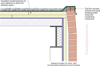 I just updated the words, just the words, not the principles. Tim Horton played defense on that team long before he got into the donut business. Photograph 2: Stains at ParapetNo drip edges. Figure 12b: Steel Stud Parapet New Pups. Large backer rod supporting a bunch of extra membrane that lets things move when they have to move. Get Inspired Any hidden voids in the construction shall be sealed and sub-divided to inhibit the unseen spread of fire and products of combustion, in order to reduce the risk of structural failure, and the spread of fire. Check out Figure 5, adapted from his book Roofs. Connect the water control element/layer of the roof to the wall, the air control element/layer of the roof to the wall, the vapor control element/layer of the roof to the wall and finally the thermal control element/layer of the roof to the wall. Figure 7: Roof Membrane TemperaturesOttawa, Canada, summer day. Did I mention the staining of the building faade? Transferring loads in multilayer compact roofs is quite controversial. The Zen approach to membrane movement. Nope, not by a long shot. All Rights Reserved. As much as it pains this old timer to say this, with the newer more dimensionally stable membranes the new pups have it more right.
  The disadvantage of this method is wasteful cutting of insulation to install between the joists, labour required to install the material and increased electrical cables required to prevent overheating, that run within the insulation. brick or stone parapet was required, with the roof set behind, as fire protection (http://en.wikipedia.org/wiki/Parapet). The roof is a key element of the building structure, providing protection from the elements and has a vital role in reducing heat loss from the building. All we have to do is apply the Baker Principles (Figure 5) to typical roofs and walls. We have provided a link on this CD below to Acrobat Reader v.8 installer. Ellen G. White quotes for installing as a screensaver or a desktop background for your Windows PC. Awesome. Required fields are marked *. There was an error submitting your subscription. We use cookies to personalise content and ads, to provide social media features and to analyse our traffic. Some of us recall that 1964 was a good year. This roof system is rarely used these days. This category only includes cookies that ensures basic functionalities and security features of the website. Photograph 4: Tear in MembraneMembrane shrinkage results in the membrane pulling apart. Explore Interiors Find Professionals that fit your criteria, share your ideas & start off on the right foot. The building shall be constructed so that the combined dead, imposed and wind loads are sustained and transmitted by it to the ground. I recommend employing mock-up walls that incorporate the project specific materials associated with the saddle flashing condition to confirm and adjust the detail so that it is constructible and sequenced properly. (1) Adapted how? Ensuring Insulation Continuity and Airti Design and Flexibility and Enhancement Achieving Thermal Continuity and Air Tig Calculation of y factor for use in DEAP Pitched Roof (Treated Veritcal Counter-Battens), Upgrade of Pitched Roof (min 3mm Plaster), Warm Roof Terrace (40mm Kingspan Optim-R Insulation), Upgrade of Pitched Roof (5mm Finishing Plaster), Flat Roof : Wall Abutment (25mm Drypacking), Flat Roof : Wall Abutment (Parralel Flange Channel Spacers), Flat Roof : Wall Abutment (Joist built into wall), Loft Ridge Dormer Detail (Heavy Duty Galvanized Hangers), Loft Ridge Dormer Detail (Bolted to Rafters), Flat Roof : Wall Abutment (Masonry Hanger). Figure 15: The Cantilevered Mini ParapetNotice that air control layer continuity is achieved by wrapping the membrane over the building corner and then constructing the cantilevered portion of the parapet over the top of this air seal. Your email address will not be published. Both of the warm roof options prevent wasteful cutting of insulation and decrease installation time, therefore labour costs. And always have drip edgesfront and backso they dont stain the building faade. In the old days it was easy; just fully adhere the roof membrane with a lot of goop directly to the structural deck so that each square foot of roof membrane stress was directly transferred to the square foot of structural deck directly under the membrane. So, projecting wooden eaves were banned in the Building Act of 1707 as a fire risk. Water control layer continuity: membranes continuous under the parapet flashing; Air control layer continuity: an air control layer in the roof assembly is connected to the air control layer in the wall assembly; Vapor control layer continuity: a vapor control layer in the roof assembly is connected to the vapor control layer in the wall assembly; Thermal control layer continuity: the thermal control layer of the roof assembly is connected to an effective thermal control layer in the wall assembly. The roof shall be constructed so that the risk of spread of flame and fire penetration from an external fire source is restricted. document.getElementById( "ak_js_1" ).setAttribute( "value", ( new Date() ).getTime() ); This site uses Akismet to reduce spam. Everything is wrong. Now we had to transfer the stress of the membrane through sometimes multiple layers of insulation before it got to the structural deck (Figure 9). This is probably the most influential graphic in my building science education. Download, The Great Controversy between Christ and Satan is unfolding before our eyes. You'll find a list of the currently available teaching aids below. The writings of Ellen White are a great gift to help us be prepared. Sound familiar? Necessary cookies are absolutely essential for the website to function properly. Some of the more common ways I have seen the ends of copings detailed include the following: 1) the coping terminates horizontally at or near the surface of the wall cladding; 2) the coping extends into the wall cladding (for example, masonry or EIFS) without an upturned leg and integral side flanges; and 3) the coping terminates within the wall cavity or cladding with an upturned leg and no side flanges. These cookies are used to collect non-sensitive data about how you interact with our website and browsing We pray these resources will enrich the lives of your students, develop their faith in God, help them grow in Christian character, and build their sense of identity with the Seventh-day Adventist Church. Courtesy of Max Baker and the National Research Council of Canada.(1). The roof of the building shall be resistant to the penetration of moisture from rain or snow to the inside of the building. Figure 4: Parapet Water ManagementKeep rainwater from getting into the top of them. These details can be a helpful starting point for design professionals but will need further development based on each projects specific building design and selection of materials. The insulation is tapered to provide a fall to the roof to enable water to run to the water outlets. A beautiful building is becoming ugly. 12501 Old Columbia Pike, Silver Spring, Maryland 20904. We have provided a download link below to Firefox 2 installer. The easiest thing to get right about parapet construction is to keep rainwater from getting into the top of them. TRADA and Approved Document Part A give guidance on sizes of joists for flat roofs relating to spans and loading. The following post includes excerpts from our book Understanding Architectural Details Residential. Consider engaging a building enclosure consultant to provide design assistance or peer review services associated with detailing and specifying the saddle flashing condition as well as other complex details and conditions. The functional requirements of the roof are: A roof is considered to be flat when it is of a slope of 1-5o to the horizontal. Join over 20,000+ active members of the FIA community and sign up to my newsletter to get all the latest news!
When I first saw it, the lightbulb went off. The firring strips allow the roof to have the slope required to enable water run off to the rain water outlets. A discussion of this has to wait for some other time. 100mm Celotex FF4000 Insulation), Beam and Block Floor (100mm Celotex FF4000 Insulation), Timber Suspended Floor (Provide cross ventilation under floor), Upgrade of ground floor (75mm Celotex GA4000 Insulation), Upgrade of a ground floor (Min 105mm thick celotex GA4000), Upgrade of a ground floor (Min 100mm thick celotex GA4000), Timber Suspended Floor (Concrete Ground Cover Min 100mm), Solid Ground Floor (65mm Concrete Sand Cement with Light Reinforcement), Tile Hung Timber Framed Wall (Using 100mm x 50mm), Tile Hung Timber Framed Wall (150mm x 50mm), Brick Finish Timber Framed Wall (100mm Celotex), Timber Frame Wall With Timber Cladding (150mm Celotex), Tile Hung Timber Framed Wall (Vapour Contol Layer), Tile Hung Timber Framed Wall (Breathable Membrane), Junction Between Solid Floor and Timber Framed Wall, Junction between Timber Suspended Floor and Timber Framed Wall, Brick Finish Timber Framed Wall (150mm x 50mm), Brick Finish Timber Framed Wall (100mm x 50mm), Eaves Detail for TImber Frame (Projecting - Boxed Eaves), Eaves Detail for Timber Frame (Clipped Eaves).