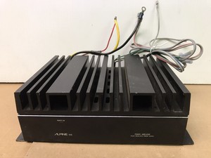
We will never try to save money/time by using an inferior, or non-direct replacement parts. The same is true for the output transistors. Pins 15 and 16 are often unused. If there is a serious problem causing excessive current draw, the fuse will help protect the amplifier. Copyright 1995-2022 eBay Inc. All Rights Reserved. Pin 7 on the TL594 is ground. If you've already read the repair information on this page and only need to see the new tips on photographing amps, click HERE. Many times, when you copy a link from the address bar (especially for something found via the search function on a site), the link will only work from the browser that was used for the search. Reference Point when Measuring Voltage: If you need internal photos of an amp to identify burned or missing components, email me at: babin_perry@yahoo.com. Sometimes they're critical and must be maintained. With no voltage on pins 8 and 11, it can't have output (most MTX, some Sony and some Xtant amps are different). Pin 15: Macro or Normal Mode: There are many different ways that an amp can fail but the two most common failures are shorted output transistors and blown power supply transistors. You do this by using a multimeter to look for low resistance connections between the transistor's terminals. It gets warm but not hot mounted like this. Troubleshooting a dead amplifier is different. 78 - Transistor Example In the name of the zipped file, include the amp model and your email address. In most instances for class A, class B or class AB amplifiers, the output transistors have to dissipate more heat than the power supply transistors and the larger case makes it easier to transfer the heat from the transistor to the heatsink because there is more surface area on the large transistor case. If you're asked to measure the voltage with the black probe on the source leg of an FET and the red probe on the gate leg of the FET and you don't know which leg is the gate and which is the source, look up the datasheet for the FET and search the datasheet for the pin configuration. Intelligent, ignorant people ask questions to learn. When you're done viewing the photo, close the window. In the case of an output transistor, the shorted transistors tries to deliver the full rail voltage to the speaker output terminal. It must be directly connected to chassis ground. The other is 3.6 ohms. Unless a potentiometer is accessible from the outside of the amplifier, you should not turn it unless you know what it is. http://www.diyaudio.com - Car Audio Forum. Don't try to be a know-it-all. repair parts amplifier alpine stereo amp power I would never have imagined that anyone would do this and I still can't understand why they do it but it's happened multiple times so it must be a widely held belief. If I have them I'll email them to you. Noise and distortion should be treated differently when asking for help with a repair. Note that the timebase is set to 2ms above (good starting point for audio, but not for the R-R carrier waveform) and is set to 5us in the image below. Lower voltage (15v) will be produced for the preamp section of the amp but the power amplifier section doesn't use a negative power supply. Amps like those made by Sony may have all green lights lit even if an amplifier has a blown power supply. Pin 11: IR_IRFZ44_NoSuffix Power Amplifier Section: Again, I used a diffuser. Amps like those made by Rockford, must have a working power supply for the power LED to be lit. Because they don't understand the operation of the various components in the vehicle well enough to troubleshoot properly, they make a guess as to what needs to be replaced and continue until they get lucky and find the defective part. Some amplifiers have DC offset protection. SK_2SC4466 This is a bias compensating transistor. Any other reading means that the transistor is defective. The power transistors in this amplifier are fully encapsulated. If set too low, the output could be distorted. To take photos with this camera, the amp has to be about 3 feet away from the lens. Most have a low opinion of mechanics that are 'parts changers'. In these two images, you see that the forward voltage drop is 0.6v. In some amplifiers, the power LED will be lit with only the remote voltage applied (B+ isn't required).
ESP When you're dealing with people who are MUCH more knowledgeable than you are about a subject and you do the same thing, you just seem like an idiot. A link to the datasheet will be provided when the results for the search are returned. At the end of this page, I've posted a couple of photos and more information that may help you in your search for a usable scope. The cathode is directly connected to the base of Q4901 (3rd leg). If you're not intelligent enough to ask properly, you're unlikely to be intelligent enough to complete the repair. THIS page tells you how to check the most common transistors. If a smaller transistor is driving a larger transistor (or a group of larger transistors), you generally refer to them as driver transistors. If I went to an advanced math forum and started using terms that I didn't understand, they would think I was an idiot and if I continued to do it, I would confirm their suspicions. Not only is the image too small, it doesn't make the most of the frame of the camera.  If you are not ordering a full stick of parts (50pcs/stick for TO-220 parts), order more than you need so you can be relatively sure you will get enough matched parts. I may have more than 100 emails and forum posts in the matter of a few days. There is a colon after each pin number so that the person filling in the blanks doesn't use hyphens (which can be mistaken for a negative sign). If you don't, at the very least, have a multimeter, there's really no way that anyone can help you. Generally, when you order parts, you get the same date code but that's not always the case. The output of the power transformer is sent to two dual rectifiers. Pin 12: If you're going to buy a camera, go to a site like the Imaging-Resource and look at the sample images (particularly the macro images) to see what the camera can do. The only time (that I can think of) that you would place the red probe on the B+ terminal is when you were measuring the voltage on the B+ terminal. The power LED is not a good indicator of the condition of an amplifier. Does that mean that there is a problem with the gain control (the amp could begin to oscillate due to an open connection in the pot) or with something that's causing the amp to shut down when the output reaches a certain level. In most class AB and class B amps (most full range amps fall into one of these categories) you will also find rail voltage on the center legs of the output transistors. If the amplifier has fully encapsulated transistors, you need to use the same type as replacements. The TL594 (or it's close relatives, the TL494 or the KA7500) produces the square wave drive signal. This page is here to help answer many of the questions that I get about basic amplifier repair. We include fedex insurance on every amplifier, but no one wants to have to fill out insurance paperwork, so package it well! Connect your black meter probe to the chassis ground terminal of the amplifier. In a day's time, I probably won't remember much of the repair and after a week, it's unlikely that I'll remember any of it without skimming over the unbroken chain of messages. There are a couple of ways to confirm that the link works universally. If you ask me for help and use chatspeak, LEET or truncated/abbreviated words (ur for you are, str8 for straight, etc), don't expect me to reply. As you can see below, Q4901 has a brown tint compared to the other D600 transistor. Professional Computer Repair Tool Precision Laptop Screwdriver Kit, XOOL 140 in 1 Electronics Repair Tool with 120 Magnetic Bits, Compatible for Macbook, iPhone, Game Console, Tablet, Skar Audio Dual 10" Complete 2,400 Watt SDR Series Subwoofer Bass Package - Includes Loaded Enclosure with Amplifier, Sony STRDH190 2-ch Home Stereo Receiver with Phono Inputs & Bluetooth Black, Hautton Precision Screwdriver Set, 126 in 1 Magnetic Screwdriver Kit, Multi-function Professional Repair Tool Kit with Portable Oxford Bag for Phone Laptop PC Watch Electronics and More -Black, 328 PCS Sleeving Wrap Wire Car Electrical Cable Tube Kits Heat Shrink Tube Tubing Polyolefin 8 Sizes Mixed Color Connector Repair Durable and Deft, Anti aging neck firming and tightening cream, All customers get FREE Shipping on orders over $25 shipped by Amazon. Don't give the voltage on each end of the component (with the black probe on ground) unless asked to do so because reading from ground to the two points is less accurate. If you don't have a digital camera, you probably know someone who will let you borrow their camera. Without the flash, the camera will slow down the shutter to produce acceptable exposure and the photo will be blurred unless you use the timer and a tripod. Some people (a lot of people) refer to all of the 3-legged components on the heatsink as MOSFETs.
  If there is no short between the center and outer legs of the rectifier, it's likely OK. The most common protection circuit is the thermal shutdown circuit. When doing this, you have to be certain that the voltage isn't dropped to a point to where it affects the output of the transistor and doesn't exceed the power rating of the dropping resistor. In most instances, most of your questions will be answered here and you will only need a bit of clarification for your specific amplifier.
  Until you know an amplifier very well, use the original parts. When using a speaker to test an amplifier, don't use an expensive or fragile speaker. The green links are photos. When power supply transistors fail dramatically (smoke, flames, soot blown out onto the board), they generally short internally (all terminals shorted together) but the high current flow causes the third leg to fuse open. This will help those helping you to ask for tests that you can perform with the tools that you have. If you're not completely familiar with the use of an oscilloscope, you need to read the oscilloscope page of this site (#73 in the directory). Q21 and Q9 are transistors. If you're interested in doing this as a side-line job, the tutorial will be a great help. The input op-amp is generally very near the RCA jacks like THIS. This is essentially a 'Cliffs-Notes' type page and isn't nearly as detailed as the tutorial I sell. Not all op-amps are in flat packages. In most amplifiers, the value of the gate resistors is between 27 and 100 ohms. When you click on it, the larger version will be displayed (as you can do with the image below).
  82 - Op-Amps When checking them with a multimeter set to 'diode check', you should find that the meter reads ~0.6v in one direction and reads as an open circuit when the probes are reversed. Sometimes very slight differences in parts can mean the difference between an amp working and not working properly. Many people are under the impression that they need an expensive 100MHz scope to troubleshoot audio circuits. When it fails, the drive circuit has no supply voltage so it cannot function. It may seem like I'm being unreasonable asking for this but this is technical and the language needs to be precise so I don't have to ask for clarification of everything you send me. The voltage amplifier drives the driver transistors and the driver transistors (2SC3421 and 2SA1358) drive the output transistors. The following image shows the parallel components for an audio amplifier. In THIS photo, the drivers are the small rectangular components with the circuit board designations Q903, Q909, Q904 and Q910. You can place the black probe on the center leg of the negative rail rectifier adjacent to Q4901 to check the base and emitter voltages. The next image is what NOT to post. Transistor Failure/Checking Transistors: When checking semiconductors, you will use a multimeter. You'll have to try your camera in both normal and macro modes. For ICs (Integrated Circuits -- chips), they can be 20+ pages long. In this amplifier, Zener diodes are used to set the regulated voltage. The original transistor can be sourced from PacParts.com. When unused, pin 15 is tied to 5v (pin 14) and pin 16 is tied to ground. The negative rail voltage would be the same distance below the reference line as this is above the reference line. It's generally due to a lack of effort to learn what the camera can or cannot do. amplifier amp audio 12v hifi digital 15w ta2024 module parts replacement mini amt customizing amp kit parts If you can use manual mode, try to use the highest F-stop/number you can. sna a01 crv 69 - Switching Power Supplies The term 'dropping resistor' describes the function of the resistor. With proper (advanced) lighting techniques or natural/ambient light, that may be ideal. Here the wire didn't need to be stripped because there was no electrical connection. In the following images, you can see that one meter reading is approximately 3.3k ohms. There is a reminder to list the IC number (circuit board designation) if there is a chance that it will be confused with another IC. Most of the other links are to web pages on this site. Motorola_MJL1302A This is a good camera but not really well suited for this type of work unless you have accessory lenses and the required adapter. It gets very confusing, especially if the original poster has additional questions about their amp. It's a general purpose resistor used to drop voltage in the circuit. If it's on the forum, copy and past the list. Also list all work that appears to have been done to the amp previously. Better photos will make it much easier for me to help you get your amp repaired. Except for a very tiny fraction of the population, that's getting them nowhere. The regulators for this amp can be seen HERE. Do you have both positive and negative regulated voltage on the power supply pins of the audio op-amps? The components that are transistors can be FETs (MOSFETs) or BJTs. amplifier The most common are over-current and thermal. You need to pull the transistors from the board for definitive testing/results. If you're asked to measure the voltage across a component (typically 2 terminal components), you place one probe on each end of that component. STMicro_TIP36C To remove them, you apply new solder to both sides, heat one end for 2-3 seconds and then move the iron to the other side. Many times, a schematic diagram or photos from an amp 'similar' to the one you have will be used for a reference. An oscilloscope isn't absolutely required for all repairs but it makes it easier to help with repairs that involve distorted output. Important! If you don't have a meter , don't run out and buy one blindly. All they seem to be able to do well is to play video games.