#include "MPU6050.h" Ideally, when PWM value is changed from 0-255, there should be a proportionate change in rpm from 0-600. So get a million errors when try to compile. But To keep things simple I have used a DC gear motor. Self-balancing robot with two ultrasonic proximity sensors and nRF24 communication + remote. Serial.println(F("FIFO overflow! distanceCm = sonar.ping_cm(); https://github.com/br3ttb/Arduino-PID-Library/blob/master/PID_v1.h, https://github.com/jrowberg/i2cdevlib/tree/master/Arduino/MPU6050. mpu.getFIFOBytes(fifoBuffer, packetSize); You will get the offset values on your Serial Monitor when you run the code given in this link. Rereading your code I see that the movement management is entrusted to the PIN blocks from 4 to 9 which, in my mBot card (MCore/Arduino uno type), I don't know what they correspond to. In file included from C:\Users\Malhar Wable\Documents\Arduino\Sketch 1\unicycle_trial_1\unicycle_trial_1.ino:9:0: sketch\MPU6050_6Axis_MotionApps20.h: In member function 'uint8_t MPU6050::dmpGetGravity(int16_t*, const uint8_t*)': sketch\MPU6050_6Axis_MotionApps20.h:689:65: warning: integer overflow in expression [-Woverflow]. { ISR(TIMER1_COMPA_vect) robot balancing self arduino instructables if(rightMotorSpeed >= 0) { #define Ki 40 The overshoots should also be reduced by now. mpuIntStatus = mpu.getIntStatus(); // get current FIFO count Pins 4 to 7 connect to the control pins of the motor driver. Question
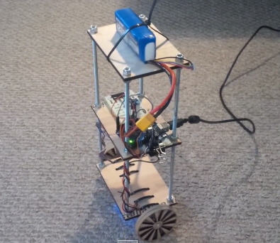
If you robot is built with a very good centre of gravity and the components are symmetrically arranged (which in most cases is not) then the value of your set-point will be 180. The robot is built on three layers of perfboards that are spaced 25mm apart using nylon spacers. The height of the robot, however, was chosen based on the availability of materials. The integral term generates a response based on the accumulated error. The orientation is constantly compared to a desired orientation through a. . We will not go much deep into this since it will be far beyond the topic. // (this lets us immediately read more without waiting for an interrupt) Watch the video at the end of this page to get an idea of how to adjust these values. I have got thie to work but am having one problem.
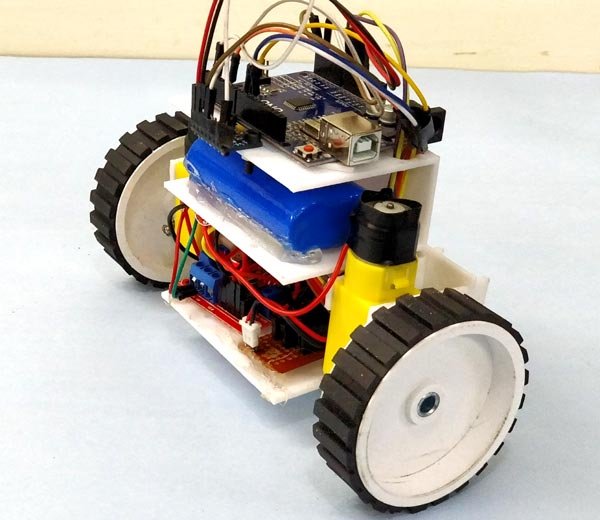
balancing robot self arduino prototype working showcase posted april pinMode (10, OUTPUT);
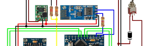
robot balancing self arduino using diagram circuit diy circuitdigest projects l298n motor smart Any suggestions? { Notice the Fritzing diagram above, connect the MPU6050 to the Arduino first and test the connection using the codes in this IMU interfacing tutorial. Robot frame (made mostly of acrylic slab) with two geared DC motors, Main circuit board, consisting of an Arduino Nano and MPU6050. setMotors(-motorPower, motorPower); analogWrite(rightMotorPWMPin, 255 + rightMotorSpeed);
 Consider balancing a broomstick on our index finger which is a classic example of balancing an inverted pendulum. robot balancing diy arduino self using projects action working The actual design was planned with the L298N drive module in the bottom rack the Arduino and battery on top of it as shown above. The top most layer has the battery, an on/off switch and the ultrasonic distance sensor (we will install this towards the end once we get the robot to balance).
 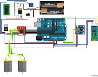 //no mpu data - performing PID calculations and output to motors pinMode(rightMotorPWMPin, OUTPUT); Solutions for 5G, smart home, industrial, automotive, healthcare, and agricultural IoT applications, TRACO Power's 180 W power supplies are offered in ultra-compact open-frame and enclosed packages, MEAN WELL's sine wave inverters offer industrial-grade high reliability, safety, and quality, Bourns' hybrid protection component combines both MOV and GDT technologies into a single component. At the moment one wheel rotates forward and the other backwards ^^, Reply
The DC motors are connected to PWM pins D6,D9 D10 and D11 respectively. Google defines complementary as "combining in such a way as to enhance or emphasize the qualities of each other or another". I reset the Arduino and it still dosent function. We read both the gravity vector and quaternion values and then compute the yaw pitch and roll value of the bot. 11 months ago. The derivative term is proportional to the derivative of the error. mpu.setZAccelOffset(963);
These readings are, in a way, complementary to each other. We use this library written by Jeff Rowberg to read the data from MPU6050. // set motor power after constraining it 0.9934 and 0.0066 are filter coefficients for a filter time constant of 0.75s. All these information can be deduced from the readings obtained from MPU6050.
At the same time we also have to control the speed at which wheels are rotating, if the bot is slightly disoriented from centre position the wheels rotate slowly and the speed increase as it gets more away from the centre position. exit status 1 Controller: The controller that I have used here is Arduino UNO, why because it is simply easy to use.
#define Kd 0.05 
The L298N module can provide the +5V needed by the Arduino as long as its input voltage is +7V or greater. } * Build on top of Lib: https://github.com/jrowberg/i2cdevlib/tree/master/Arduino/MPU6050 So my bot did not look as I planned in initial stage.
In between the motors is a 9V battery for the motor driver. Serial.print("S"); gyroX = mpu.getRotationX(); Lastly, set the Ki.
1 year ago. I have to figure out how to fix it. { The PID output variable also decides how fast the motor has to be rotated. For our self-balancing robot, the angular velocity along the x-axis alone is sufficient to measure the rate of fall of the robot.
The self-balancing robot is essentially an inverted pendulum. TIMSK1 |= (1 << OCIE1A);
Thanks for your time.
} The orientation is constantly compared to a desired orientation through a PID loop.
robot balancing self wheel arduino diagram circuit controlled android battery
setMotors(motorPower, motorPower);
It is easier to build a full-sized balancing robot than it is to build a small one like ours.
if (devStatus == 0) Alm disso, quando eu rodo o cdigo todo, ele no reconhece nada do init_PID. Since we assume that the MPU6050 will return 180 when the bot is upright. balancing This should be sufficient to steer the robot away from the obstacle. If these minor correction dint work and still if the bot is falling down we increase the speed of the motor. If you are not familiar with these two components then it is recommended to read through MPU6050 Interfacing and L298N Motor driver tutorial.
mpu.initialize(); // verify connection The current orientation of the bot is monitored by the MPU6050. Did you make this project? digitalWrite(rightMotorDirPin, HIGH); arduino analogWrite(leftMotorPWMPin, leftMotorSpeed); Serial.print("R"); Why am I getting errors in Arduino IDE testing saying: I want to clear these errors as soon as possible, can somebody help ?
mpu.setYAccelOffset(1593); accY = mpu.getAccelerationY(); robot balancing arduino self code controlling DC motor using L293D and Arduino. #define rightMotorPWMPin 5 Chassis: Another place where you should not compromise is with your bots chassis. The position of the MPU6050 when the program starts running is the zero inclination point. Forward(); //Rotate the wheels forward
Serial.begin(9600); sei(); // enable global interrupts Accelerometer and Gyroscope: The best choice of Accelerometer and Gyroscope for your bot will be the MPU6050. (estou usando o Arduino Due), Great project, but im not smart enough to change the motor direction :-| Can you tell me what I have to do? }. Try moving the robot forward and backward while keeping it tilted at some fixed angle. The ultrasonic distance sensor that I've used is the US-020. // set compare match register to set sample time 5ms Serial.println(F("Initializing I2C devices")); To drive the motors we need some information on the state of the robot.
mpu.setDMPEnabled(true); // enable Arduino interrupt detection Waiting for first interrupt")); accAngle = atan2(accY, accZ)*RAD_TO_DEG; { We will first complete the circuitry and structure of the robot. In other words, the accelerometer reading gets affected by short duration signals and the gyroscope reading by long duration signals.
It will simply fall over. Would you be so kind as to explain their function?Thank you! packetSize = mpu.dmpGetFIFOPacketSize(); Glad to hear your appreciation. Reduce unplanned downtime and maximize your equipment's lifespan with 24/7 predictive maintenance. /******End of values setting*********/. pinMode(13, OUTPUT); {
The MPU6050 has a 3-axis accelerometer and a 3-axis gyroscope. First we include the libraries that are required for this program to work.
This is very important. #define targetAngle -2.5. // set the motor control and PWM pins to output mode Submitted by The Black Switch on Sun, 01/09/2022 - 17:53. { This is a tiny robot measuring 4 inches wide and 4 inches tall and is based on the Arduino Pro Mini development board and the MPU6050 accelerometer-gyroscope module. else
It won't stay steady.
Tangible Coding provides an opportunity for kids to become involved in programming with no screen used.
}, void init_PID() {
if (input>150 && input<200){//If the Bot is falling analogWrite(10,output); The angle of inclination will be measured with respect to this point. Thank You for your reply.Just yesterday I tried to change state of "if (leftMotorSpeed> = 0) { analogWrite (leftMotorPWMPin, leftMotorSpeed); digitalWrite (leftMotorDirPin, LOW);" in HIGHT and I took the next one to LOW, and it finally stopped spinning around z and started going back and forth.I tried to reset "#define targetAngle -0.0" and it seems to be even better (I didn't understand what it was for).Now I'll have to set up PID carefully to eliminate an annoying snap when beating forward. We have to check if the bot is leaning towards the front or towards the back using the MPU6050 and then if its leaning towards the front we have to rotate the wheels in forward direction and if it is leaning towards the back we have to rotate the wheels in the reverse direction. mpuInterrupt = true; TCCR1B = 0; // same for TCCR1B When I switched on the robot, the program freezes intermittently. Pins 8 & 9 interface with the ultrasonic sensor module.Hope this clarifies. Inside the main loop function we check if the data from the MPU6050 is ready to be read. Battery: We need a battery that is as light as possible and the operating voltage should be more than 5V so that we can power our Arduino directly without a boost module. Submitted by Aswinth Raj on Fri, 04/03/2020 - 10:30, In reply to Awesome works great ! Maybe I'll write to you again if I need it, if I don't disturb. 4. Participated in the Microcontroller Contest 2017. The 3-axis gyroscope of MPU6050 measures angular rate (rotational velocity) along the three axes.
fifoCount = mpu.getFIFOCount(); // check for overflow (this should never happen unless our code is too inefficient)
Pins 5 & 6 are speed control pins (PWM pins) for right and left motor respectively. The accelerometer measures acceleration along the three axes and the gyroscope measures angular rate about the three axes.
double setpoint= 176; //set the value when the bot is perpendicular to ground using serial monitor. robot arduino balancing } The on-board regulator on the Arduino board will convert the input 7.4V to 5V and the ATmega IC and MPU6050 will be powered by it. gyroX = mpu.getRotationX(); If data is now displayed on the serial monitor, you're good to go! Hammond's rugged enclosures available in twenty sizes, three colors, and with accessory inner panels.
Did u fix that or know the why is happening? What we are trying to do here is to keep the center of gravity of the robot exactly above the pivot point. Motors: The best choice of motor that you can use for a self balancing robot, without a doubt will be Stepper motor. on Step 9. attachInterrupt(0, dmpDataReady, RISING); It can be balanced better if the center of mass is higher relative to the wheel axles. The DC motors can run from voltage 5V to 12V. #include "Wire.h"#include "I2Cdev.h"
This is due to the horizontal component of acceleration interfering with the acceleration values of y and z-axes. You will know why at the end of this article. You can also check our dedicated article on using MPU6050 with Arduino.
Note that if you are planning to use a supply voltage of more than +12V for the L298N module, you need to remove the jumper just above the +12V input. We move our finger in the direction in which the stick is falling.
1 year ago. // toggle the led on pin13 every second
We need to connect them to PWM pins because we will be controlling the speed of the DC motor by varying the duty cycle of the PWM signals. { We will get correction values positive when the bot is falling towards front and we will get values in negative if the bot is falling towards back.
this arduino robot called Otto robot. How would I do this considering my battery has only two connecting wires? C:\Users\MALHAR~1\AppData\Local\Temp\ccPqjIcb.ltrans0.ltrans.o: In function `dmpInitialize': sketch/MPU6050_6Axis_MotionApps20.h:332: undefined reference to `MPU6050::reset()', sketch/MPU6050_6Axis_MotionApps20.h:343: undefined reference to `MPU6050::setSleepEnabled(bool)', sketch/MPU6050_6Axis_MotionApps20.h:347: undefined reference to `MPU6050::setMemoryBank(unsigned char, bool, bool)', sketch/MPU6050_6Axis_MotionApps20.h:349: undefined reference to `MPU6050::setMemoryStartAddress(unsigned char)', sketch/MPU6050_6Axis_MotionApps20.h:354: undefined reference to `MPU6050::setMemoryBank(unsigned char, bool, bool)', sketch/MPU6050_6Axis_MotionApps20.h:363: undefined reference to `MPU6050::getXGyroOffsetTC()', sketch/MPU6050_6Axis_MotionApps20.h:364: undefined reference to `MPU6050::getYGyroOffsetTC()', sketch/MPU6050_6Axis_MotionApps20.h:365: undefined reference to `MPU6050::getZGyroOffsetTC()', sketch/MPU6050_6Axis_MotionApps20.h:375: undefined reference to `MPU6050::setSlaveAddress(unsigned char, unsigned char)', sketch/MPU6050_6Axis_MotionApps20.h:377: undefined reference to `MPU6050::setI2CMasterModeEnabled(bool)', sketch/MPU6050_6Axis_MotionApps20.h:379: undefined reference to `MPU6050::setSlaveAddress(unsigned char, unsigned char)', sketch/MPU6050_6Axis_MotionApps20.h:381: undefined reference to `MPU6050::resetI2CMaster()', sketch/MPU6050_6Axis_MotionApps20.h:388: undefined reference to `MPU6050::writeProgMemoryBlock(unsigned char const*, unsigned int, unsigned char, unsigned char, bool)', sketch/MPU6050_6Axis_MotionApps20.h:395: undefined reference to `MPU6050::writeProgDMPConfigurationSet(unsigned char const*, unsigned int)', sketch/MPU6050_6Axis_MotionApps20.h:399: undefined reference to `MPU6050::setClockSource(unsigned char)', sketch/MPU6050_6Axis_MotionApps20.h:402: undefined reference to `MPU6050::setIntEnabled(unsigned char)', sketch/MPU6050_6Axis_MotionApps20.h:405: undefined reference to `MPU6050::setRate(unsigned char)', sketch/MPU6050_6Axis_MotionApps20.h:408: undefined reference to `MPU6050::setExternalFrameSync(unsigned char)', sketch/MPU6050_6Axis_MotionApps20.h:411: undefined reference to `MPU6050::setDLPFMode(unsigned char)', sketch/MPU6050_6Axis_MotionApps20.h:414: undefined reference to `MPU6050::setFullScaleGyroRange(unsigned char)', sketch/MPU6050_6Axis_MotionApps20.h:418: undefined reference to `MPU6050::setDMPConfig1(unsigned char)', sketch/MPU6050_6Axis_MotionApps20.h:420: undefined reference to `MPU6050::setDMPConfig2(unsigned char)', sketch/MPU6050_6Axis_MotionApps20.h:423: undefined reference to `MPU6050::setOTPBankValid(bool)', sketch/MPU6050_6Axis_MotionApps20.h:426: undefined reference to `MPU6050::setXGyroOffsetTC(signed char)', sketch/MPU6050_6Axis_MotionApps20.h:427: undefined reference to `MPU6050::setYGyroOffsetTC(signed char)', sketch/MPU6050_6Axis_MotionApps20.h:428: undefined reference to `MPU6050::setZGyroOffsetTC(signed char)', sketch/MPU6050_6Axis_MotionApps20.h:439: undefined reference to `MPU6050::writeMemoryBlock(unsigned char const*, unsigned int, unsigned char, unsigned char, bool, bool)', sketch/MPU6050_6Axis_MotionApps20.h:443: undefined reference to `MPU6050::writeMemoryBlock(unsigned char const*, unsigned int, unsigned char, unsigned char, bool, bool)', sketch/MPU6050_6Axis_MotionApps20.h:446: undefined reference to `MPU6050::resetFIFO()', sketch/MPU6050_6Axis_MotionApps20.h:449: undefined reference to `MPU6050::getFIFOCount()', sketch/MPU6050_6Axis_MotionApps20.h:454: undefined reference to `MPU6050::getFIFOBytes(unsigned char*, unsigned char)', sketch/MPU6050_6Axis_MotionApps20.h:457: undefined reference to `MPU6050::setMotionDetectionThreshold(unsigned char)', sketch/MPU6050_6Axis_MotionApps20.h:460: undefined reference to `MPU6050::setZeroMotionDetectionThreshold(unsigned char)', sketch/MPU6050_6Axis_MotionApps20.h:463: undefined reference to `MPU6050::setMotionDetectionDuration(unsigned char)', sketch/MPU6050_6Axis_MotionApps20.h:466: undefined reference to `MPU6050::setZeroMotionDetectionDuration(unsigned char)', sketch/MPU6050_6Axis_MotionApps20.h:469: undefined reference to `MPU6050::resetFIFO()', sketch/MPU6050_6Axis_MotionApps20.h:472: undefined reference to `MPU6050::setFIFOEnabled(bool)', sketch/MPU6050_6Axis_MotionApps20.h:475: undefined reference to `MPU6050::setDMPEnabled(bool)', sketch/MPU6050_6Axis_MotionApps20.h:478: undefined reference to `MPU6050::resetDMP()', sketch/MPU6050_6Axis_MotionApps20.h:482: undefined reference to `MPU6050::writeMemoryBlock(unsigned char const*, unsigned int, unsigned char, unsigned char, bool, bool)', sketch/MPU6050_6Axis_MotionApps20.h:486: undefined reference to `MPU6050::writeMemoryBlock(unsigned char const*, unsigned int, unsigned char, unsigned char, bool, bool)', sketch/MPU6050_6Axis_MotionApps20.h:490: undefined reference to `MPU6050::writeMemoryBlock(unsigned char const*, unsigned int, unsigned char, unsigned char, bool, bool)', sketch/MPU6050_6Axis_MotionApps20.h:493: undefined reference to `MPU6050::getFIFOCount()', sketch/MPU6050_6Axis_MotionApps20.h:498: undefined reference to `MPU6050::getFIFOBytes(unsigned char*, unsigned char)', sketch/MPU6050_6Axis_MotionApps20.h:507: undefined reference to `MPU6050::readMemoryBlock(unsigned char*, unsigned int, unsigned char, unsigned char)', sketch/MPU6050_6Axis_MotionApps20.h:510: undefined reference to `MPU6050::getFIFOCount()', sketch/MPU6050_6Axis_MotionApps20.h:516: undefined reference to `MPU6050::getFIFOBytes(unsigned char*, unsigned char)', sketch/MPU6050_6Axis_MotionApps20.h:525: undefined reference to `MPU6050::writeMemoryBlock(unsigned char const*, unsigned int, unsigned char, unsigned char, bool, bool)', sketch/MPU6050_6Axis_MotionApps20.h:530: undefined reference to `MPU6050::setDMPEnabled(bool)', sketch/MPU6050_6Axis_MotionApps20.h:539: undefined reference to `MPU6050::resetFIFO()', sketch/MPU6050_6Axis_MotionApps20.h:540: undefined reference to `MPU6050::getIntStatus()', C:\Users\Malhar Wable\Documents\Arduino\Sketch 1\unicycle_trial_1/unicycle_trial_1.ino:63: undefined reference to `MPU6050::setXGyroOffset(int)', C:\Users\Malhar Wable\Documents\Arduino\Sketch 1\unicycle_trial_1/unicycle_trial_1.ino:64: undefined reference to `MPU6050::setYGyroOffset(int)', C:\Users\Malhar Wable\Documents\Arduino\Sketch 1\unicycle_trial_1/unicycle_trial_1.ino:65: undefined reference to `MPU6050::setZGyroOffset(int)', C:\Users\Malhar Wable\Documents\Arduino\Sketch 1\unicycle_trial_1/unicycle_trial_1.ino:66: undefined reference to `MPU6050::setZAccelOffset(int)', C:\Users\Malhar Wable\Documents\Arduino\Sketch 1\unicycle_trial_1/unicycle_trial_1.ino:73: undefined reference to `MPU6050::setDMPEnabled(bool)', C:\Users\Malhar Wable\Documents\Arduino\Sketch 1\unicycle_trial_1/unicycle_trial_1.ino:78: undefined reference to `MPU6050::getIntStatus()'.