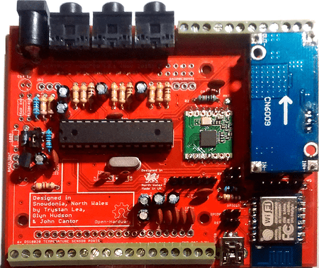
 On this picture you can see everything whats used in production: https://blog.danman.eu/wp-content/uploads/2018/04/IMG_20180316_155349_HDR.jpg, Data format is simple json: https://github.com/danielkucera/ble-meter-mbed/blob/master/src/main.cpp#L114. From the docs: Operating principle: A pulse magnet in the first moving drum of the index type Z3/Z6 activates a reed switch in the pulse transmitter. So you get pulses from reed switch (open circuit/closed circuit). In my meter, the pulse length was contant (38 ms as far as I could see). However, to ensure a clear '0' and '1' I choose to add a LM293 comparator.
 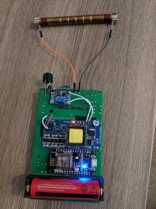 I know. You can find the documentation here Here's the "hello world" tutorial to give you the most beginner context. I'd been thinking about trying to sniff the wireless data. You can also set frequency that your sensor will report the power consumption by updating SEND_FREQUENCY. esp8266 wired The software then configures BLE advertisement which contains JSON with current counter value and measured battery voltage.
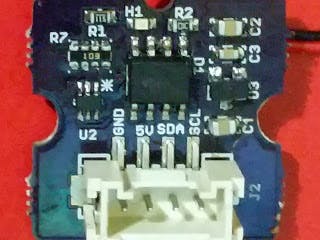
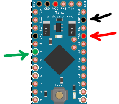
Learn how your comment data is processed. my power meter sits inside my safety cabinet. In the App SDK, there's this Auth API which lets you perform user authentication in the app. esp8266 ninja masking I think its not bad for my first 3D design. This mode requires constant power so you will need to connect the sensor to an electrical outlet. There are two outputs on the electricity meter you have on the picture. My meter was showing 11mA at 4.5V which was way too high for battery powering. May someone please give me a hint which one and how to connect which cable to which GPIO PIN? Will my app contain all the power meters I ever sold till date?
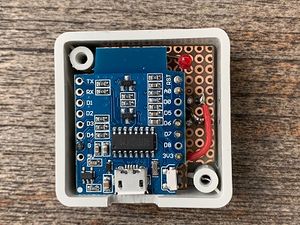
Share it with us! I'm designing my power meter from the same commercial and production point of view as Moiz did: a company producing power meters and selling it to real users. It kept me believing it has to be possible to make the module work when I had absolutely no hopes. Nevertheless, I chose the second option because software is cheaper and easier to debug than an electrical circuit. This is the very first prototype of my power meter. Let's see how I integrated Grandeur and built the app. count_mode (Optional): Configure how the counter should behave With this discharge tempo it should last (3.16V 1.8V) / ((3.16V 2.98V)/30days) = cca 226 days BUT the discharge profile of cheapest zinc-carbon battery looks like this: As you can see the discharge rate is highest in the beginning and then decreases and stabilizes so I guess it will last at least twice that long. The principle of operation is simple: Normally it is in sleep. https://esphome.io/cookbook/power_meter.html, https://www.amazon.de/gp/product/B071P98VTG/ref=ppx_yo_dt_b_asin_title_o00_s00?ie=UTF8&psc=1, https://forum.arduino.cc/index.php?topic=416054.0. Is the source code available? Im using Wemos D1 MINI and I have connected output pin 20 to D1 pin on Wemos and output pin 21 to ground on Wemos. meter pulse esp8266 power logger nodemcu running produces script working Now let's move to the second issue. Have a look at the tasmota firmware. Timestamping each summary packet with the time of the update helps me plot the current and power on a timeseries graph in my web app. esp8266 weather When I click on it, I see it's current and power graphs getting plotted on data coming from my power meter in real-time. (in 6 places). Then I tried to directly connect 3.3V voltage (behind regulator) and checked the current: 28uA was very nice result so I had to find the problem. geiger diy counter instructables screen touchscreen After 21 months (16. The pulses are detected by an ESP8266. This sensor counts LED pulses from your house meter and converts it into Watts and accumulated KWh. Im using Tasmota built in Counter functionality. nodemcu esp8266 meter pulse power logger arduino sensor thalin phototransistor running patrik wifi temperature 6c ide projects raspberry pi There needs to be a mechanism that shows a user only his/her devices when he/she opens the web app. By connecting a 0.6 V to Vin and the phototransistor the Vref, I got a positive signal in the dark, and a negative signal at the pulse. power, and the time of the update, and updates the old summary on the Cloud with the new one. esp8266 openenergymonitor I dont have the knowledge to help you here. 12. The pulse counter sensor allows you to count the number of pulses and the frequency of a signal
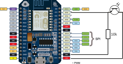
Well I saw the smart air cooler project by Moiz where he switched the cooler on/off from his web app and I thought of extending it a little. The default is 3 times per minute (every 20 seconds). What it'd do, under the hood, is it'll pair that power meter with that user account making that account the owner of that device, and only he/she can see the device data. The MySensors Arduino library handles the wireless radio link and protocol Grandeur naturally rejects all requests coming from unknown origins for security, therefore we need to add localhost:3000 to project's allowed origins list. esp8266 That's how simple the circuit looks like: I powered the current sensor with 3.3V (via the ESP) and connected its output to the analog input of the ESP. As posted above, i have purchaesed this ESP32. I had some disturbation with exterior light and therefor do a check on the pulse length. That's when Grandeur came to the rescue. I like to use PlatformIO (PIO) so I decided to use it again. 4 years ago. Now that we know the base platform I'd develop my power meters on, let's officially define our project: An IoT power meter using ESP8266 and ACS712 current sensor that would send current and power readings to the app where I'd push those readings to a graph in real-time. Each customer would have to register his/her account on the web app when he/she buys a device from me for the very first time. , I implemented the login functionality in my app which let me build up a user's profile and show him the data of only those devices that he paired with. Unfortunately the sensor cannot report the current consumption in Watts because the sensor can not track time while sleeping; the elapsed time between two blinks is required to calculate the current consumption in Watts. project by Moiz where he switched the cooler on/off from his web app and I thought of extending it a little. I also purchaes these photo transistors. count the light pulses on a power meter, you can do the following: When the total sensor is configured, the pulse_counter also reports the total The program is published on my Github: https://github.com/Wim3d/Main_power_meter.
I used ESP8266 and at that time EasyESP but I already converted it to ESPHome. Thanks a lot for pointing at these errors. When a user logs into the app, he/she sees empty list, and an "Add a device" button, on clicking which he could enter the device ID (which I would print on the device itself), and that device would be added to his/her devices list. Disassembled sensor can be seen on this page. First step was to discover how does the measurement work. It then prepares a summary packet containing the RMS current as current, power, and the time of the update, and updates the old summary on the Cloud with the new one. and is only meant for delivering a proof of concept since the focus of this project is more around the software segment. If you enable this, set up the count_mode to increase on the falling edge, not leading edge. Now to implement this, I went through the most common tools out there including Blynk. for fetching summary updates from the Cloud, and then put up current and power graphs from that data using chart.js. It sends the output data to my MQTT broker. This means I can build register/login functionalities. When a user logs in, how will the app know which devices (from the devices that I sold) does this particular user own? esp8266 nodemcu oximeter /* esp8266 modul sensoren sleep hausautomation elektrotechnik programmieren haustechnik sicherheitssysteme pi wifi wake instructables informatik To fit 70 pulses in a second, your meter will have shorter pulses than 38 ms. Maybe the pulselength changes at different frequencies. // Minimum time between send (in milliseconds). So it's settled. maxim counting pulses hackster things project Defaults to 60s. On logging in, I see my PM-1 power meter that I registered earlier from the Cloud Dashboard. I checked this, but found out that in my version of the power meter the IR communication is not implemented, apparently it is quite a basic version, only with holes, bu no IR-LEDs. When I click on it, I see it's current and power graphs getting plotted on data coming from my power meter in real-time.
The sensors forms a self healing radio network with optional repeaters. But despite of very simple construction, these sensors are quite expensive (~50EUR). Or just #yolo and test. document.getElementById( "ak_js_1" ).setAttribute( "value", ( new Date() ).getTime() ); This site uses Akismet to reduce spam. It has support for nrf51 with both Arduino and Mbed frameworks. on the ESP32. However, due to the use of the pulse counter peripheral, a maximum of 8 channels can be used! To get the data in, I connected USB bluetooth adapter with added antenna and wrote a simple data relay script in python: When everything was working on a bench, I measured the dimensions and created a box derived from the original sensor clip. About: I like to combine electronics like Arduino's, ESP8266 etc with 3D designing and 3D printing. Here's how it looks while running: We log into the app with the email and password we gave our. I use my router power supply of 12V and found out that a LM1117 is not very efficient and gets quite hot.
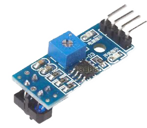
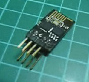
Of course will need to drop to 3.3V at the ESP. And you can use a magent to mount a IR-LED. meter sensor pulse water tcrt5000 switch reflective ir infrared photoelectric line track power barrier mysensors meters openhardware io Just deep sleep, wait for interrupt from reed switch, shout new value, sleep again. When it came I did the measurement: 145.3uA is a decent result so I concentrated on consumption at count and transmit phase. esp8266 If your meter has a visible to the naked eye blinking light then any Photoresistor well work. Aliexpress search showed one very cheap and compact BLE module so I gave it a try. Grandeur handles device communications with Cloud over the web, which means we first need to connect our ESP to internet which is what ESP8266WiFi library is for. Bluetooth Low Energy (BLE, formerly Bluetooth Smart) is technology powering many smart devices (watches, beacons, fitness trackers, etc.) What photo resistor to use for the power meter? But the Arduino SDK requires my project's API Key and my device's ID to know which device in which project are we referring to when setting summary. https://forum.arduino.cc/index.php?topic=416054.0. Our power meter can measure current and power, so here's how I defined them in the model: Since we cannot use (or test) our device without a user, I created the first user of my product from the, To test my device, I paired it with my user directly from the. One for receiving and one for sending. Feels neat! Inspired by wireless thermometers I started to experiment with 433MHz transmitters and receivers. Okay then. 1 year ago, Dear Mads, thanks for your comment. The appropiate voltages were found by using potentiometers for the Vin and the Vref voltage. The sensor defaults to measuring its values using a unit of measurement 1.5V) therefore Vref ? total (Optional): Report the total number of pulses. time is detected, its discarded and no pulse is counted. // Less than an hour since last pulse, use microseconds, // more thAn an hour since last pulse, use milliseconds as micros will overflow after 70min, // Fetch last known pulse count value from gw, // Use the internal pullup to be able to hook up this sketch directly to an energy meter with S0 output, // If no pullup is used, the reported usage will be too high because of the floating pin, // Send the sketch version information to the gateway and Controller, // Only send values at a maximum frequency or woken up from sleep, // Check that we don't get unreasonable large watt value, which, // could happen when long wraps or false interrupt triggered. Any ideas? So I thought what if we could see how our appliance is consuming power and tune our usage around that and eventually reduce our electricity bills by a few percent. Will try to add the resistor and give feedback if this works for me. @carlb peripheral Are you using LDR to detect the blinking LED of meter?
While controlling an appliance from phone is cool, it doesn't save you any money, right! It is not clear for me, at the end, have used the expansion board in the box? . network topology allowing messages to be routed to nodes. The measuring device has to be small, look professional and have low power consumption so it can run on batteries. relay arduino sensor pulse moisture water mysensors distance power meter vcc soil motion dht temperature air humidity 5v connected build Device auth token helps in validating the device's authenticity. Tune the sensitivity/trigger level by adjusting the trim potentiometer on the sensor board. esp8266 I wasnt satisfied with the result because I wanted it to last at least one year on batteries so I started to look for another solution. Here's how I paired them together: To build up program for ESP8266 on Arduino IDE, I used. It also has the pairing feature that I need. I suggest to change the minimal pulse length (PULSE_MIN_LENGTH in line 18 of my code) to 5 ms. Simplifying IoT dev; abridging that huge gap between our softwares and hardwares. esp8266 neat The gas meter is directly in the hallway so everyone can see it. I tried to use a photoresistor to make a tachometer but it's too slow to handle that job. Grandeur is designed to be straight forward and have a seamless yet powerful integration in your IoT products. The expansion board was used only for developing, its not inside the final product. My first choice for making IoT device was esp8266 module, specifically NodeMCU Amica which I had at hand. Read the values in Openhab to get these cool graphs! To build my app, I used Grandeur's JS SDK for fetching summary updates from the Cloud, and then put up current and power graphs from that data using chart.js. I have a similar power meter and the right one is sending a full "SML-Datagram" with consumption, voltage, current, and may more. For example, if youre using the pulse counter with a photodiode to I used magnetic contact for detecting pulses, source code is here: https://github.com/danielkucera/ble-meter-mbed (but it doesnt compile anymore ). The power meter shows the current and power consumption graphs in the web app on my phone. predefines the variables that the IoT product would have and which will later be fetched/updated from the device-end or the app-end. If you are reading these lines Im glad my post interested and maybe inspired you. Surely one of is the mentioned GPIO PIN12 as mentiones in the code. Will my app contain all the power meters I ever sold till date? I used some more sticky putty to prevent ambient light shining into the phototransistor as I opened the case in daylight. Your email address will not be published. reflexlichtschranke esp8266 It is important to drill a hole at the exact position of the LED. At the moment, on the same ESP8266 I have: I like to do the pulse counter for power meter but there is no ready power source at the meter! Ill post an update after batteries die. // Number of blinks per kWh of your meter. But i still got no data from this. Fantastic idea! It's an important difference. Try requesting it again. number of pulses measured. It took me days to find working config for Mbed and I tried many many things. See this image: https://ae01.alicdn.com/kf/HTB1ZIbibL1H3KVjSZFHq6zKppXao/DDS518L-120-230.jpg. Grandeur is designed to be straight forward and have a seamless yet powerful integration in your IoT products. Another important consideration is the fact that ACS712 should only be used for subsystem monitoring and it is highly, to use it for power monitoring of entire home. On the ESP32, this sensor is even highly accurate because its using the hardware pulse counter The pulses are quite weak so I needed some suitable electronic components.
Required fields are marked *. pulse sensor optical openenergymonitor guide setup Defaults to DISABLE. A new version has been release since you last visited this page: 2022.6.2 . However i did not follow through to the end because I went a different route (my meter sends radio signals I went with This ). Powered by Discourse, best viewed with JavaScript enabled.